Bob needed some walker skis. I had printed some many times as the abrasiveness of the pavement and friction wear them out. I dug up the file and printed some that I had many times before.
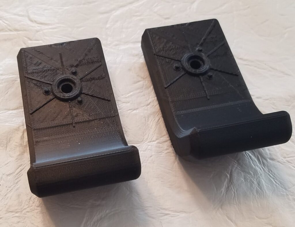
This design was printed to fit some rubber boots that slipped over the walker leg pipes. The unit was held on by a screw, nut and washers.
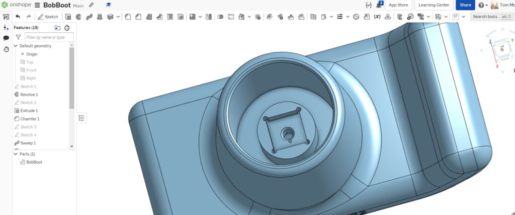
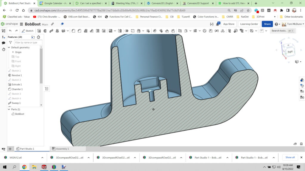
Bob took these home only to realize that his system was slightly different. The pipe ends were a molded cup with a screw holding an insert for the internal diameter of the pipe. My first thought was to print some boots in Nylon that would adapt the the skis. I started that design project in Onshape sketching and revolving the shape without detailed dimensions. I called the file, BobBoot. When finished I thought, “why not just print the whole thing and use his inserts?” Here’s the result. Hidden is the fancy boss on the bottom of the cup that locks the insert from rotating and accepts a screw to hold it in place.
“BobBootSki”
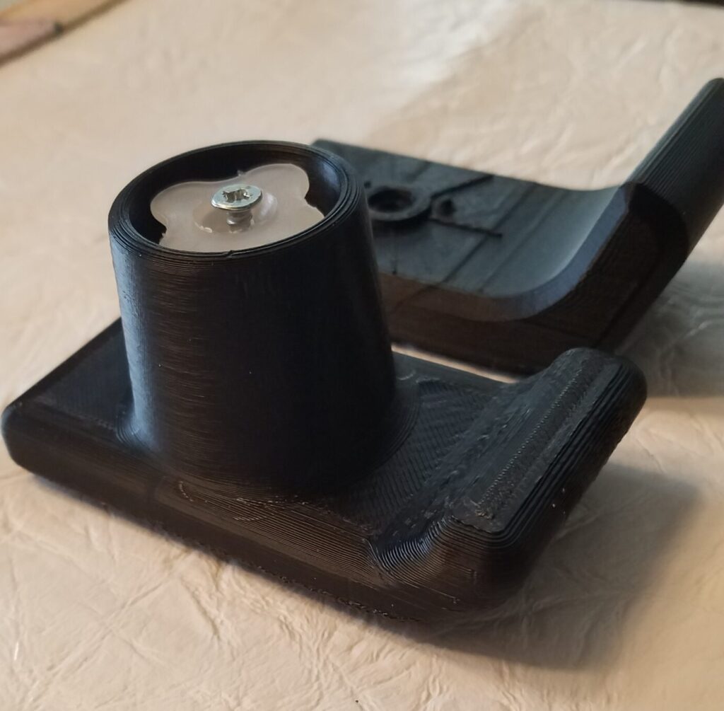
I added detailed dimensions and developed the boss to receive the insert. When finished I thought, “might as well add the ski!” With a quick rectangle and ski profile I swept the ski attached to the boot. Now the device is called the “BobBootSki.”
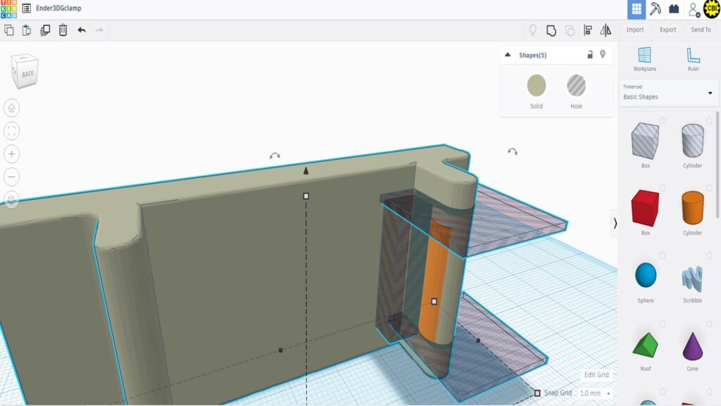
Details of the boot, screw hole and anti-rotate square pocket of the “BobBootSki.”Cutaway view of “BobBootSki”
Parts were printed in ABS on Cat’sPaw (FF Creator).
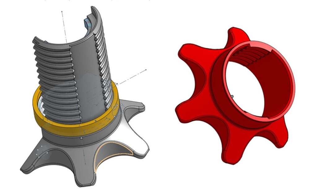
Bruce from the E3 club introduced the sleeve adapter for the spool holder he found on Thingiverse. It was tweaked in a number of ways.
The design fits the Ender 3 post but was too big for the Killer class machines we have so a thickness ring was added. The original design stl was imported into Onshape and the ring was added.
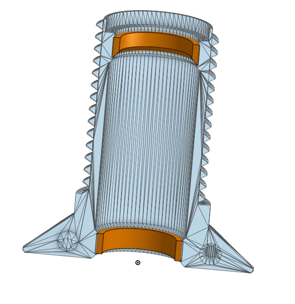
The thread form was traditional 60 degrees. When printing this sags in one direction.This didn’t make it super easy to spin. The sleeve was redrawn in Onshape with a round semicircle thread form. All parts were adapted with a semicircle thread form. A lot of turning is required when you have a large opening in the spool hub.
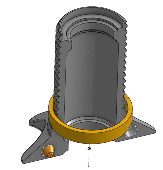
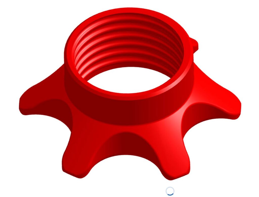
The “spikes” on the wedge portions of the bolt and nut were hard on the fingers. A more relaxed ergonomic design was developed.
To minimize the amount of turning a split thread was developed borrowing from wood vices of the past.
The four parts are shown here.
1/2 spool holder with original threads and spacers inserted1/2 spool holder with round thread form and nut that holds the two halves to the spool holder.The rounded threads and rounded spokesModified thread form,rounded spokes and split threads
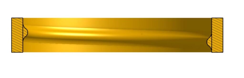
Note the semicircular thread form in the section view here.
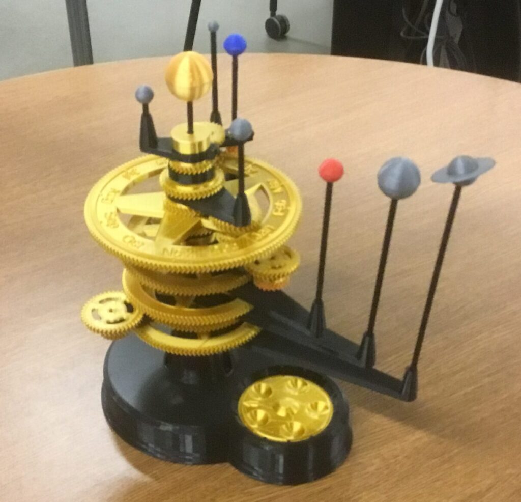
My friend Dave is an astronomer and was intrigued by mechanical Orrery’s and especially one that could be 3D printed. This one was found on the internet. The idler gears in the original design were two separate gears with a pin to connect them. The pin was made as part of the print on one gear. The pin is a crossed boss into crossed slots on the other gear. Various other tweaks for smooth operation.
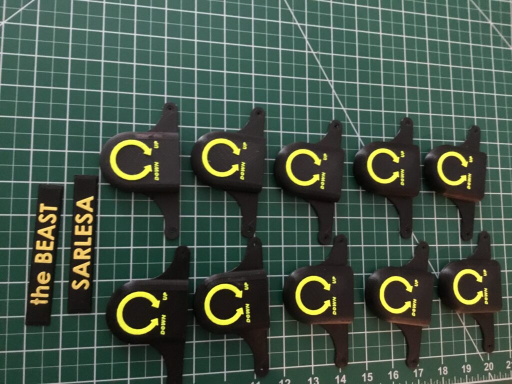
TPM Technologies Ender3 fan covers and nameplates for Build Your Own workshop.
Our Ender 3 club has developed a number of enhancements for the Ender 3 beyond the offset square. The Makerspace at Cumberland Business Incubator sponsors a Build Your Own class for the Ender 3. Eleven embellishments are included in the class. Here is a shot of a few of them. The fan covers started with a monochrome stl downloaded from Thingiverse. The stl file was imported into TinkerCAD. Then, converted to two stl files by taking a thin slice at the start of the lettering to allow the letters to be printed in a different color. Using the dual extrusion wizard in Simplify3D the files were processed into one build file and printed on Killer, a Flashforge Creator Pro machine. The nameplates were developed in Solidworks and two stl files extracted to follow the same workflow for printing.
Parts were printed in ABS on Killer class (FlashForge Creator Pro) machines.
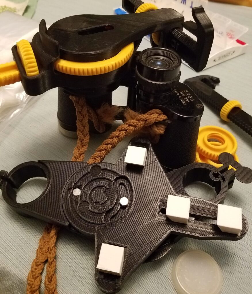
TPM Technologies Smart Phone to eyepiece adapters. Test fit on binoculars.
Buddy Bob wanted some smart phone adapters for a telescope. Searched on Thingiverse and found many to choose from. Here is a couple of the choices selected.
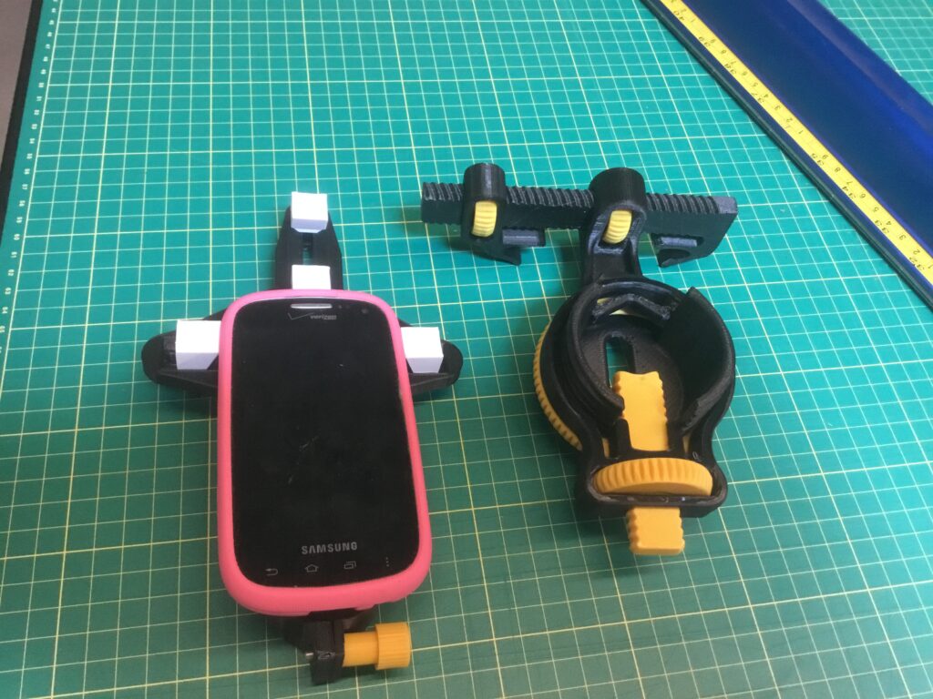
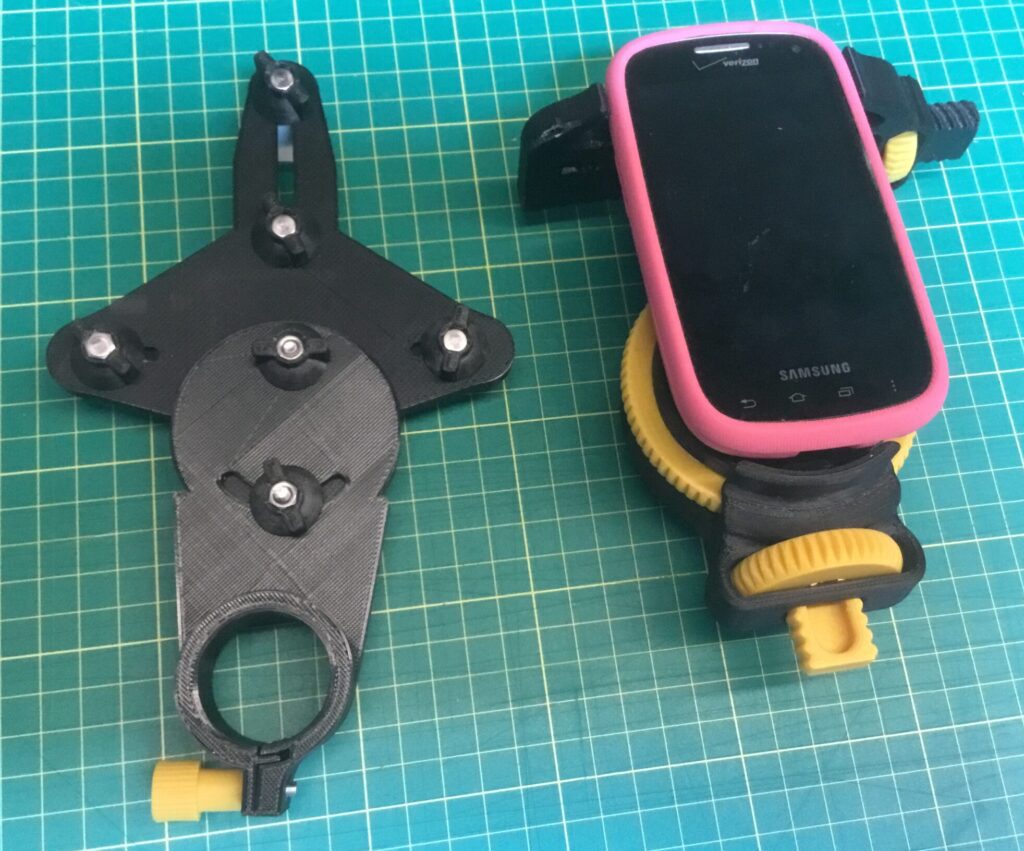
TPM Technologies Test fit for smart phone.
Some parts were remixed. Thumbnut and Thumbscrew pieces were fit for 4mm Hex head screws. These were applied to the phone locking mechanism. A more traditional thumbscrew knob was used for the eyepiece clamp. The original eyepiece diameter was 1.35 inch and was redesigned for a 1.25 inch diameter using SolidWorks. The phone clamps on the open ocular unit were modified to be even with the smart phone surface using TinkerCAD.
Parts were printed in ABS on Killer class (FlashForge Creator Pro) and Makerbot Replicator and in PLA on Ender 3’s.
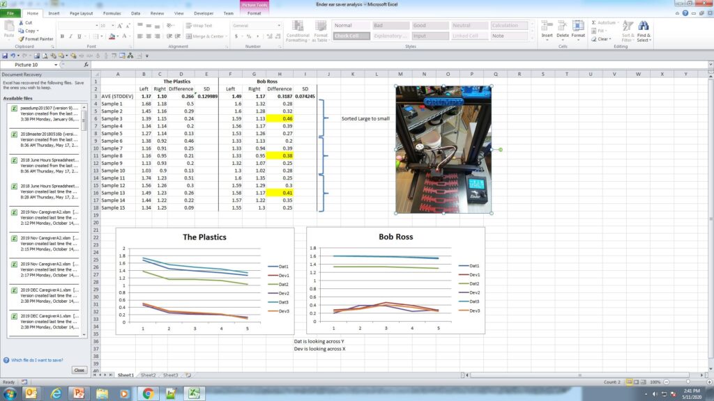
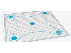
An infographic of sort identifying the data from 3 different part runs of 5 parts each for both Bob Ross and The Plastics Ender 3 printers. The picture identifies the orientation of the pieces on the build plate.
A Tale of two Ender 3’s…
“Bob Ross” and “The Plastics” (TP) both exhibited some strange printing behavior via the data. The clips were measured for depth on the left side and the right side. The deviation was calculated from the left side to the right side. The data was ordered in decreasing value of the 5 part run based on the left hand readings. (Note this is the side the Z-axis screw is mounted on the Ender 3.) Let’s examine these individually starting with Bob Ross.
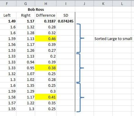
Data of 15 straps in batches of 5 on Bob Ross
It should be noted that the mask strap is a nominal 2 mm in height.
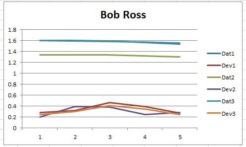
The measurements for each batch of 5 are listed. The data was sorted by decreasing value within each dataset. The deviation of depth was calculated from left to right. Two datasets were plotted for each batch. Dat is the left data and Dev is the difference data. The SD or Standard Deviation was calculated for all 15 differences. The average difference in all 15 is .31mm and the SD is 0.07. In the Ender 3 configuration the Dat values will represent the variation in the Y axis and the Dev values will represent variation in the X direction. Of interest is the small rise in data point #3 in each batch. As the data are not necessarily in order of placement on the machine it is difficult to surmise exactly the reason. In future measurements the order of placement will be noted.
Note the consistency of deviation in the Dat values on Bob Ross. Dat1 and Dat3 are nearly identical.
It should be also noted that Bob Ross and The Plastics both have aluminum plates and polymer covers for the build plate.
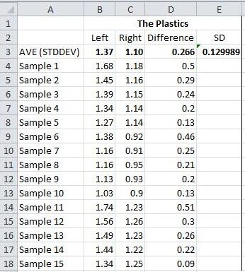
Data for 15 Mask Clips in batches of 5 from The Plastics Ender 3
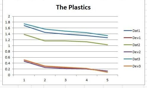
The Plastics part runs exhibited repeatable trends with side to side deviations averaging less than those on Bob Ross. The standard deviation of the 15 parts was almost 50% greater however. The deviations are very consistent as shown in the graph with Dev1, Dev2, and Dev3 nearly colinear.
Interesting correlation on X and Y deviations on The Plastics Ender 3.
Besides just alignment the data shows something else must be happening. As the heated bed is spring loaded and the X axis is noticeably askew one can’t help but wonder if there is some multi-dimensional pressure at work.
Ender 3 TP had a skew on the X-axis rail. Conceivably the table was parallel to the rail via the alignment springs and screws.
THE SOLUTION:
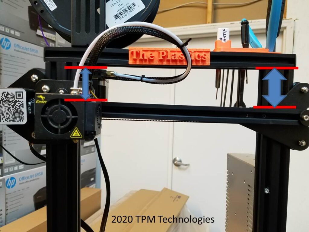
The fix was to develop a method for establishing a perpendicular or square relationship between the rollers on the z axis and the X-axis extrusion beam. The offset in the Y-dimension makes it difficult to use an ordinary square during assembly. To complicate matters the relationship that is critical is where the rollers form a line that needs to be perpendicular to the X-axis extrusion. The mounting screws of the sheet metal pieces to the T-nuts on the extrusion can allow a considerable skew.
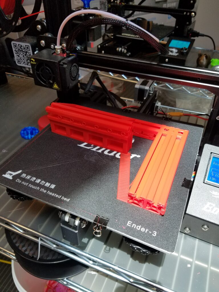
Bob Ross Ender 3 printing the offset square.
The square developed has a facsimile 20×40 rail with a 20×20 extension at the right offset to aid in assembling the roller plate and extrusion in a perpendicular relationship. The 20×40 section is inserted into the roller assembly to establish the roller line of travel. The printed 20×20 extrusion is mated to the X-axis extrusion beam to verify alignment. The fasteners can be loosened and the square used to establish the square relationship. See Part 3.
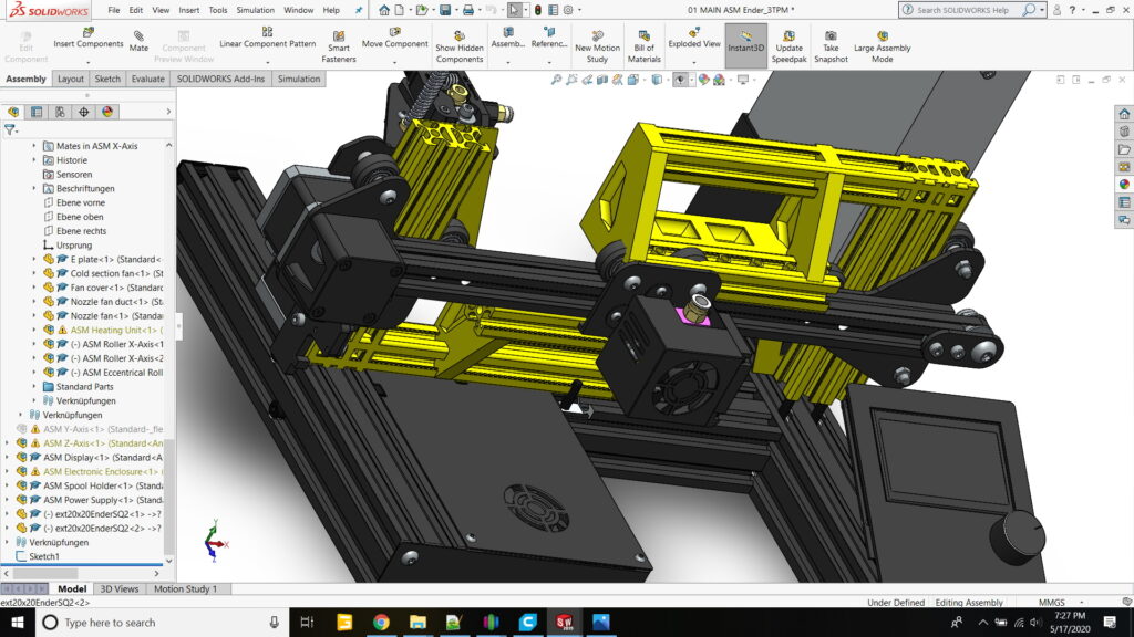
The Square was designed in SolidWorks leveraging models in the public domain for the extrusions. Luckily, someone had also made available the whole Ender 3 as an assembly so testing the fit of the design was relatively easy. In this figure you can see the offset square in both orientations to determine the squareness of both the X-axis motor mount (left side) and the belt take-up bracket (right side).The square is mirrored in the two applications to deal with the offset of the X-axis beam to the rollers. From the left the bottom of the extrusion is aligned and from the right the top of the extrusion is used.
The offset square shown in both orientations to align both the Ender 3 X-axis motor mount and idler bracket. Luckily someone had already developed a SolidWorks model so developing the square was relatively easy. In this view the vertical uprights are hidden and the square inserted and mated to the X-axis extrusion beam. Note the offset in the Y-direction to match up with the location of the extrusion.
THE FIRST TEST
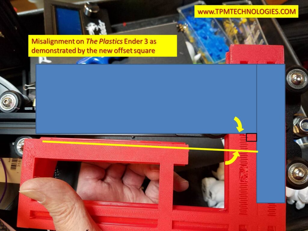
The x-axis assembly is removed from The Plastics Ender 3 and the offset square inserted to review the alignment. OOPS. The easiest way to align and square the X-axis to the guide rollers that travel vertically.
The offset square was exported from SolidWorks, sliced in Simplify3D and printed on Bob Ross. The x-axis assembly was removed from The Plastics and the square used to see how far askew the idler bracket was. Stay tuned for Part Three where we describe the realignment procedure and test the results!!
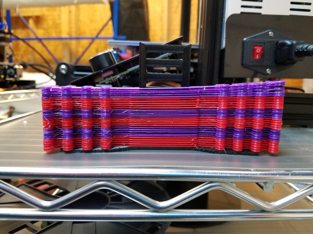
What’s wrong with this picture? Surgical mask clips stacked up show alignment issues on “The Plastics” Ender 3
A Tale of two Ender 3’s…
“Bob Ross” and “The Plastics” (TP) were printing surgical mask ‘ear saver’ clips. A friend wanted 40 of them for his audiologist friend as they found they were very helpful for not interfering with hearing aids when using masks. Upon further inspection with a caliper the clip on the right side of the machine (opposite of the Z axis screw) was considerably smaller than the left. Also, in a batch of 5 some variation was exhibited front to back.
In the picture, Bob Ross was printing red and TP was printing purple. Bob Ross fared better but still there was some variation. See part two for details. The X-axis beam on TP was noticeably oblique to the frame.
Ender 3 TP had a skew on the X-axis rail. Conceivably the table was parallel to the rail via the alignment springs and screws.
To make a long story short (See part three for the conclusion) an offset square was developed. It is a little tricky as the important relation is the line formed by the vertical rollers on the z-axis carriage and the extrusion beam that the extruder or X-axis carriage rides on. The mounting screws of the sheet metal pieces to the T-nuts on the extrusion can allow a considerable skew. The parallelism can be accommodated by adjusting the spring loaded tensioners on the heated bed. But once measurements were taken something seemed amiss. (See data analysis in part two.)
THE PUNCH LINE:
The square developed has a facsimile 20×40 rail with a 20×20 extension at the right offset to aid in assembling the roller plate and extrusion in a perpendicular relationship. Once TP was realigned, the next batch of parts looked extremely promising and we are awaiting the results quantitatively.
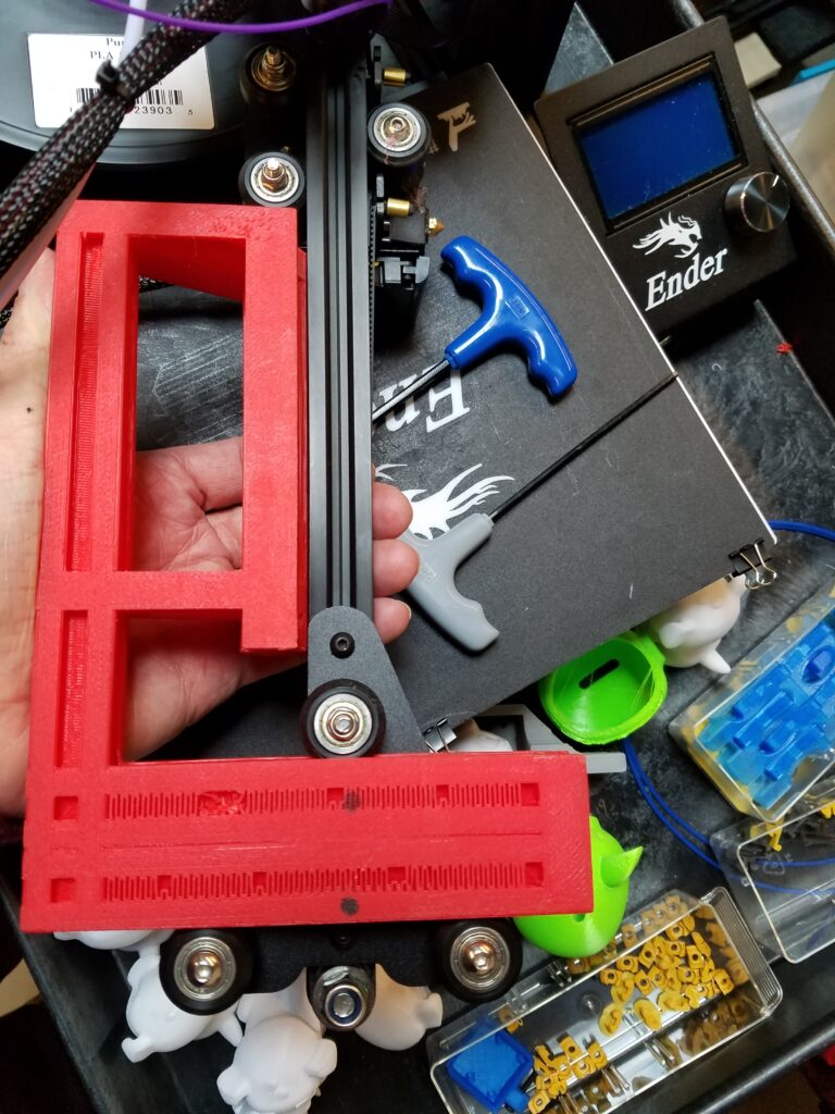
A special square assembly aid designed and 3D printed on an Ender3 for setting the proper relationship between the z-axis rollers and the X-axis beam.
Stay tuned for Part Two and Part Three where we analyze the data, describe the realignment procedure and test the results!!
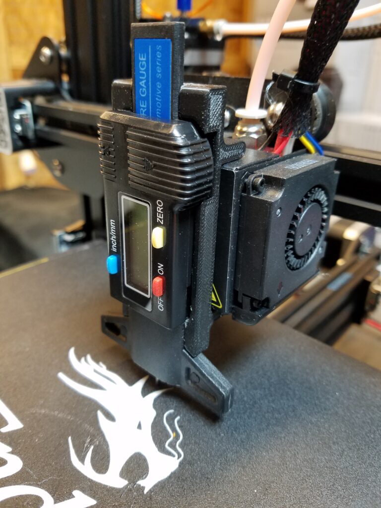
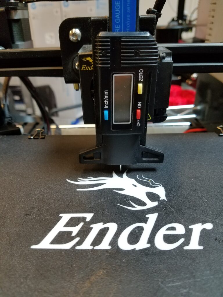
A nice bracket to hold the tire check gage was found for Ender 3. (Thingiverse #3732166 ) This simple bracket holds the tire gage clipping around the extruder fan casing. It is a nice concept but we found there needs to be a shim to make it fit tight enough that the readings are accurate. Either printed with spring tensioning slots or some kind of clamp would be an improvement. A future project! Having tested many levels with a piece of paper for a shim stock looking at numbers is sort of a soothing relief. As we want to check the tram when everything is to temperature the bracket was printed in ABS.
After a while it was a bit tedious to position the table and extruder by hand so time for some programming.
The autoleveling routine found on Thingiverse (# 2987803 ) was modified to remove the printing code and just go from location to location to check with the depth gage. The routine has stops at each position and waits for the operator to push the button to proceed to the next position.
THE RESULT:
Because you don’t want the nozzle to drag on the table a clearance offset of 40 mm was used to move from measurement spot to measurement spot and then 30 mm for the measurement point in Z.
The tire gage plunger is not spring loaded and has to be applied manually but this is OK once the bracket is secure on the extruder housing.
As the bracket attaches to the extruder fan box it is not tight and easy to bump out of place. To make the bracket “clip” tighter some modifications were added via TinkerCAD. A couple of slots and an extra bump made the bracket nice and tight and give more consistent measurements.
Note the negative material slots and the extra bump in orange to provide a “spring” to pressure the clamp on the extruder fan.
The original bracket was uploaded into TinkerCAD and the modifications shown grouped and then downloaded. The part was sliced in Simplify3D and printed on and Ender 3 in PLA.
An infographic of sort identifying the data from 3 different part runs of 5 parts each for both Bob Ross and The Plastics Ender 3 printers. The picture identifies the orientation of the pieces on the build plate.
A Tale of two Ender 3’s…
“Bob Ross” and “The Plastics” (TP) both exhibited some strange printing behavior via the data. The clips were measured for depth on the left side and the right side. The deviation was calculated from the left side to the right side. The data was ordered in decreasing value of the 5 part run based on the left hand readings. (Note this is the side the Z-axis screw is mounted on the Ender 3.) Let’s examine these individually starting with Bob Ross.
Data of 15 straps in batches of 5 on Bob Ross
It should be noted that the mask strap is a nominal 2 mm in height.
The measurements for each batch of 5 are listed. The data was sorted by decreasing value within each dataset. The deviation of depth was calculated from left to right. Two datasets were plotted for each batch. Dat is the left data and Dev is the difference data. The SD or Standard Deviation was calculated for all 15 differences. The average difference in all 15 is .31mm and the SD is 0.07. In the Ender 3 configuration the Dat values will represent the variation in the Y axis and the Dev values will represent variation in the X direction. Of interest is the small rise in data point #3 in each batch. As the data are not necessarily in order of placement on the machine it is difficult to surmise exactly the reason. In future measurements the order of placement will be noted.
Note the consistency of deviation in the Dat values on Bob Ross. Dat1 and Dat3 are nearly identical.
It should be also noted that Bob Ross and The Plastics both have aluminum plates and polymer covers for the build plate.
Data for 15 Mask Clips in batches of 5 from The Plastics Ender 3
The Plastics part runs exhibited repeatable trends with side to side deviations averaging less than those on Bob Ross. The standard deviation of the 15 parts was almost 50% greater however. The deviations are very consistent as shown in the graph with Dev1, Dev2, and Dev3 nearly colinear.
Interesting correlation on X and Y deviations on The Plastics Ender 3.
Besides just alignment the data shows something else must be happening. As the heated bed is spring loaded and the X axis is noticeably askew one can’t help but wonder if there is some multi-dimensional pressure at work.
Ender 3 TP had a skew on the X-axis rail. Conceivably the table was parallel to the rail via the alignment springs and screws.
THE SOLUTION:
The fix was to develop a method for establishing a perpendicular or square relationship between the rollers on the z axis and the X-axis extrusion beam. The offset in the Y-dimension makes it difficult to use an ordinary square during assembly. To complicate matters the relationship that is critical is where the rollers form a line that needs to be perpendicular to the X-axis extrusion. The mounting screws of the sheet metal pieces to the T-nuts on the extrusion can allow a considerable skew.
Bob Ross Ender 3 printing the offset square.
The square developed has a facsimile 20×40 rail with a 20×20 extension at the right offset to aid in assembling the roller plate and extrusion in a perpendicular relationship. The 20×40 section is inserted into the roller assembly to establish the roller line of travel. The printed 20×20 extrusion is mated to the X-axis extrusion beam to verify alignment. The fasteners can be loosened and the square used to establish the square relationship. See Part 3.
The Square was designed in SolidWorks leveraging models in the public domain for the extrusions. Luckily, someone had also made available the whole Ender 3 as an assembly so testing the fit of the design was relatively easy. In this figure you can see the offset square in both orientations to determine the squareness of both the X-axis motor mount (left side) and the belt take-up bracket (right side).The square is mirrored in the two applications to deal with the offset of the X-axis beam to the rollers. From the left the bottom of the extrusion is aligned and from the right the top of the extrusion is used.
The offset square shown in both orientations to align both the Ender 3 X-axis motor mount and idler bracket. Luckily someone had already developed a SolidWorks model so developing the square was relatively easy. In this view the vertical uprights are hidden and the square inserted and mated to the X-axis extrusion beam. Note the offset in the Y-direction to match up with the location of the extrusion.
THE FIRST TEST
The x-axis assembly is removed from The Plastics Ender 3 and the offset square inserted to review the alignment. OOPS.
The offset square was exported from SolidWorks, sliced in Simplify3D and printed on Bob Ross. The x-axis assembly was removed from The Plastics and the square used to see how far askew the idler bracket was. Stay tuned for Part Three where we describe the realignment procedure and test the results!!