A Tale of two Ender 3’s…
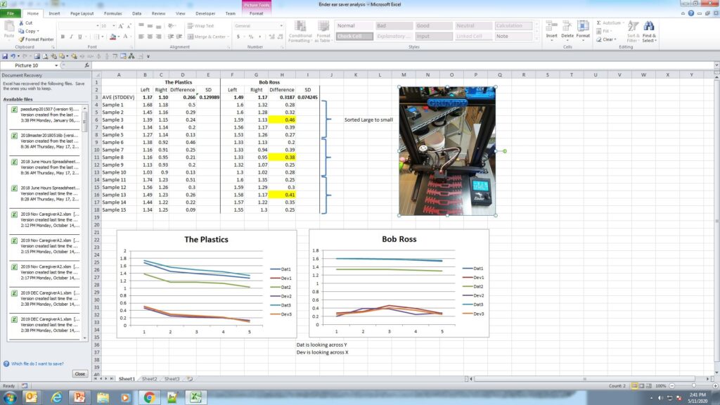
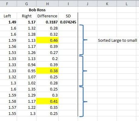
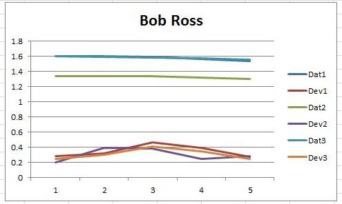
“Bob Ross” and “The Plastics” (TP) both exhibited some strange printing behavior via the data. The clips were measured for depth on the left side and the right side. The deviation was calculated from the left side to the right side. The data was ordered in decreasing value of the 5 part run based on the left hand readings. (Note this is the side the Z-axis screw is mounted on the Ender 3.) Let’s examine these individually starting with Bob Ross.
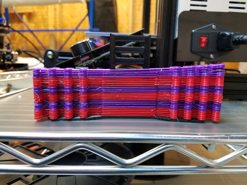
It should be noted that the mask strap is a nominal 2 mm in height.
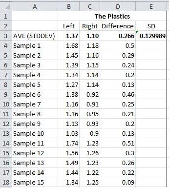
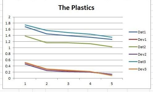
The measurements for each batch of 5 are listed. The data was sorted by decreasing value within each dataset. The deviation of depth was calculated from left to right. Two datasets were plotted for each batch. Dat is the left data and Dev is the difference data. The SD or Standard Deviation was calculated for all 15 differences. The average difference in all 15 is .31mm and the SD is 0.07. In the Ender 3 configuration the Dat values will represent the variation in the Y axis and the Dev values will represent variation in the X direction. Of interest is the small rise in data point #3 in each batch. As the data are not necessarily in order of placement on the machine it is difficult to surmise exactly the reason. In future measurements the order of placement will be noted.
It should be also noted that Bob Ross and The Plastics both have aluminum plates and polymer covers for the build plate.
The Plastics part runs exhibited repeatable trends with side to side deviations averaging less than those on Bob Ross. The standard deviation of the 15 parts was almost 50% greater however. The deviations are very consistent as shown in the graph with Dev1, Dev2, and Dev3 nearly colinear.
Besides just alignment the data shows something else must be happening. As the heated bed is spring loaded and the X axis is noticeably askew one can’t help but wonder if there is some multi-dimensional pressure at work.
THE SOLUTION:
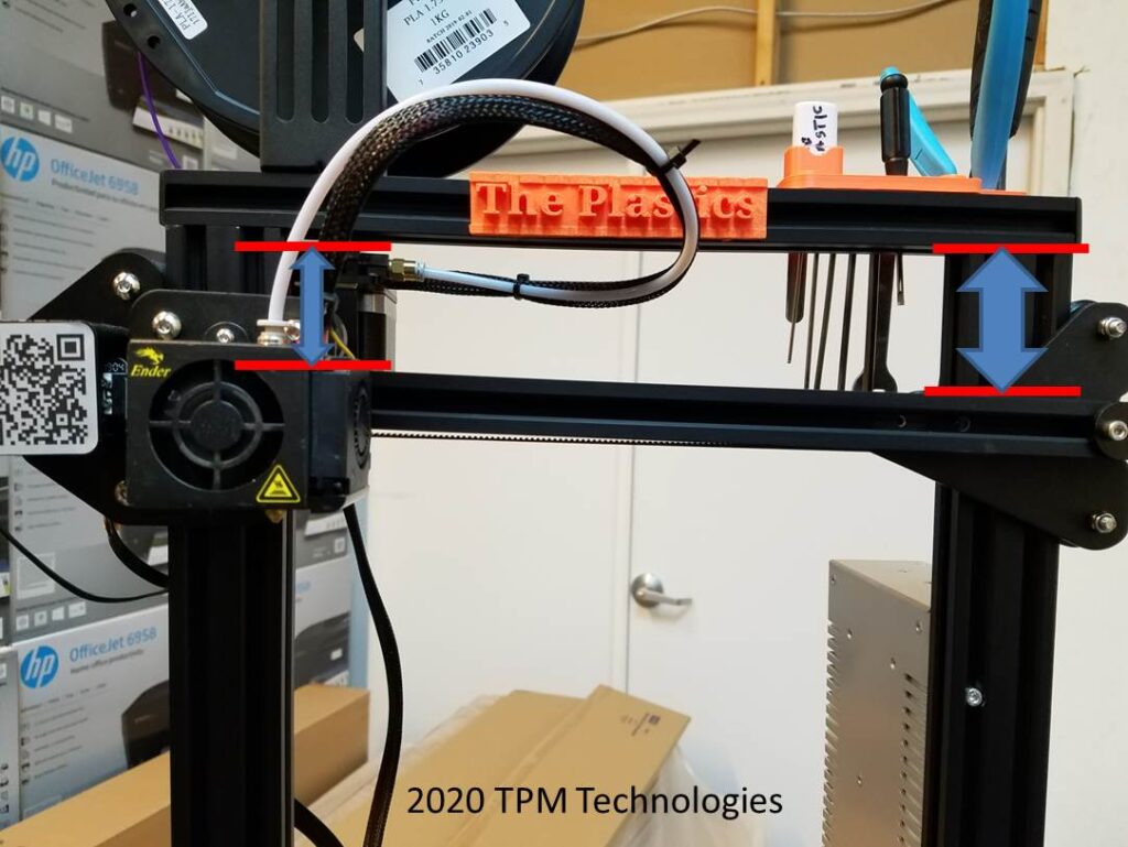
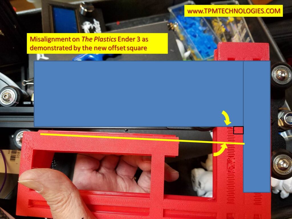
The fix was to develop a method for establishing a perpendicular or square relationship between the rollers on the z axis and the X-axis extrusion beam. The offset in the Y-dimension makes it difficult to use an ordinary square during assembly. To complicate matters the relationship that is critical is where the rollers form a line that needs to be perpendicular to the X-axis extrusion. The mounting screws of the sheet metal pieces to the T-nuts on the extrusion can allow a considerable skew.
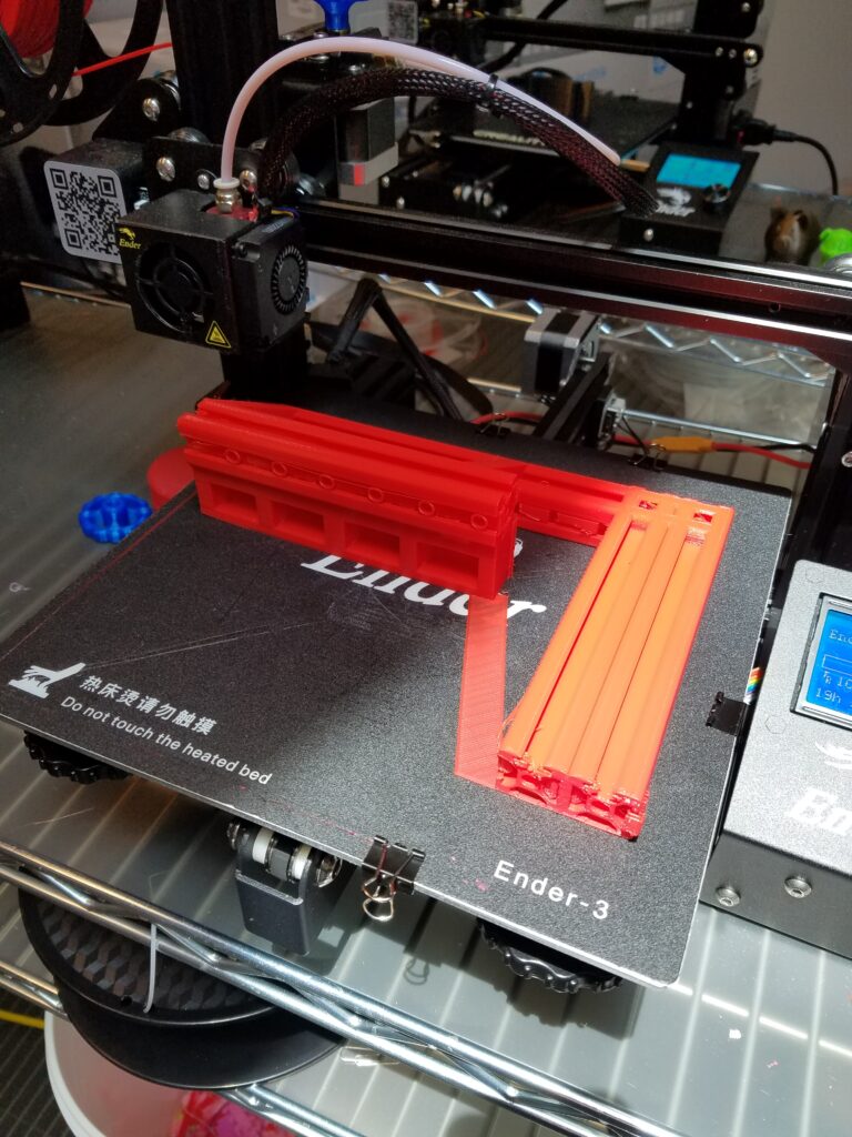
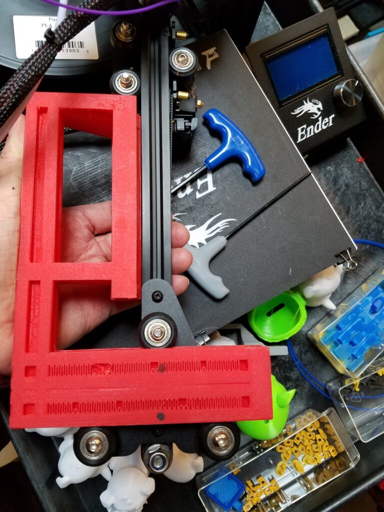
The square developed has a facsimile 20×40 rail with a 20×20 extension at the right offset to aid in assembling the roller plate and extrusion in a perpendicular relationship. The 20×40 section is inserted into the roller assembly to establish the roller line of travel. The printed 20×20 extrusion is mated to the X-axis extrusion beam to verify alignment. The fasteners can be loosened and the square used to establish the square relationship. See Part 3.
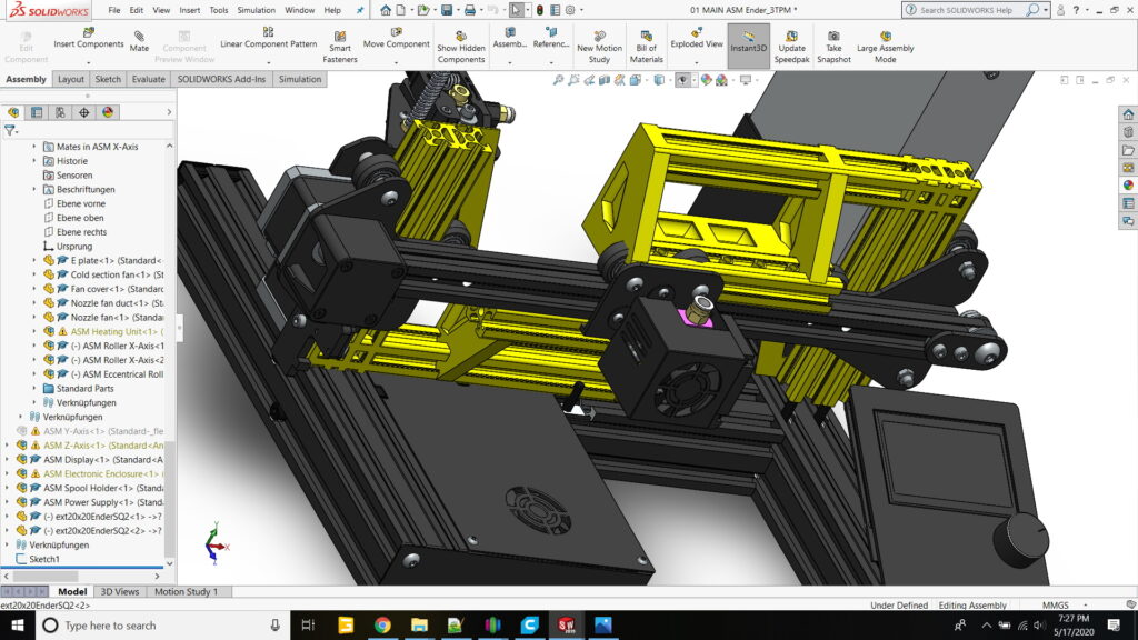
The Square was designed in SolidWorks leveraging models in the public domain for the extrusions. Luckily, someone had also made available the whole Ender 3 as an assembly so testing the fit of the design was relatively easy. In this figure you can see the offset square in both orientations to determine the squareness of both the X-axis motor mount (left side) and the belt take-up bracket (right side).The square is mirrored in the two applications to deal with the offset of the X-axis beam to the rollers. From the left the bottom of the extrusion is aligned and from the right the top of the extrusion is used.
THE FIRST TEST
The offset square was exported from SolidWorks, sliced in Simplify3D and printed on Bob Ross. The x-axis assembly was removed from The Plastics and the square used to see how far askew the idler bracket was. Stay tuned for Part Three where we describe the realignment procedure and test the results!!