3D Printing Projects 202006 – Squaring up the Ender 3 X-axis Part One

What’s wrong with this picture? Surgical mask clips stacked up show alignment issues on “The Plastics” Ender 3

A Tale of two Ender 3’s…

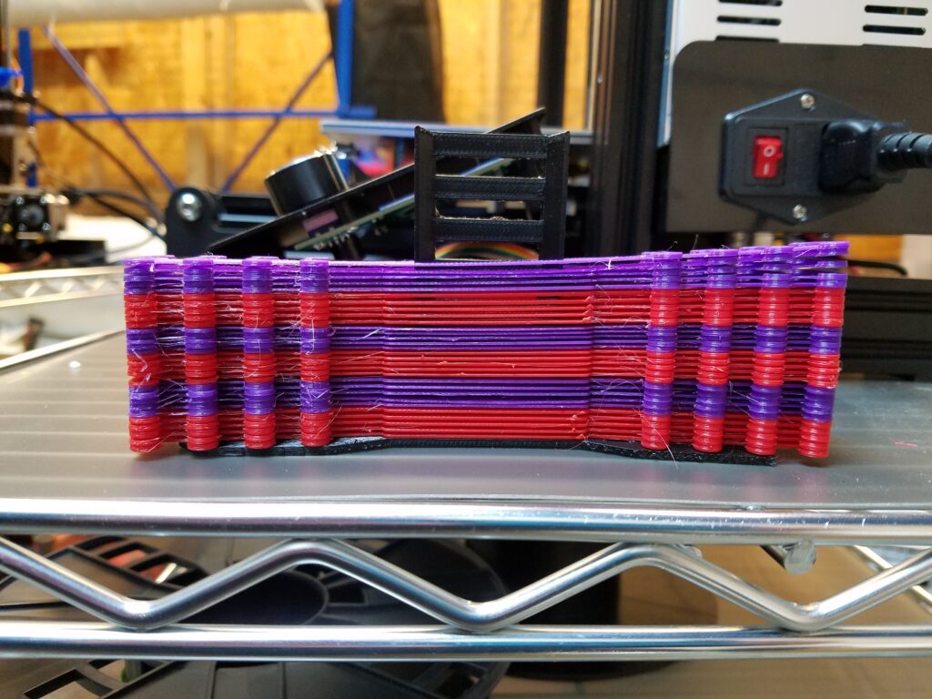
“Bob Ross” and “The Plastics” (TP) were printing surgical mask ‘ear saver’ clips. A friend wanted 40 of them for his audiologist friend as they found they were very helpful for not interfering with hearing aids when using masks. Upon further inspection with a caliper the clip on the right side of the machine (opposite of the Z axis screw) was considerably smaller than the left. Also, in a batch of 5 some variation was exhibited front to back.

In the picture, Bob Ross was printing red and TP was printing purple. Bob Ross fared better but still there was some variation. See part two for details. The X-axis beam on TP was noticeably oblique to the frame.

Ender 3 TP had a skew on the X-axis rail. Conceivably the table was parallel to the rail via the alignment springs and screws.

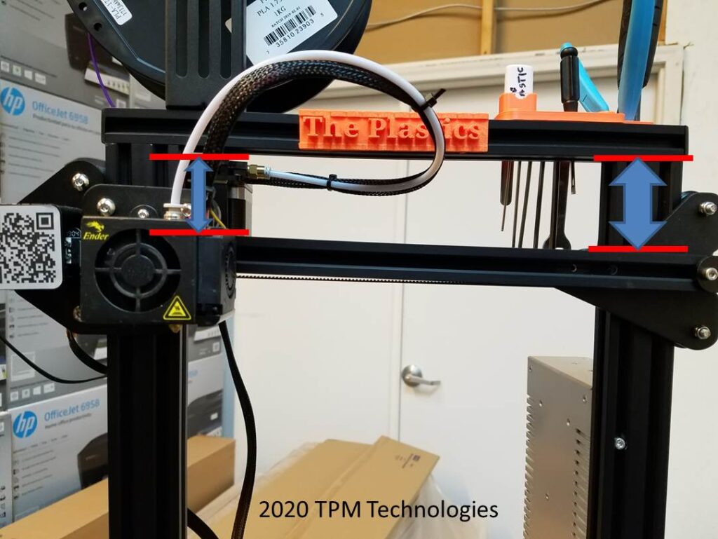
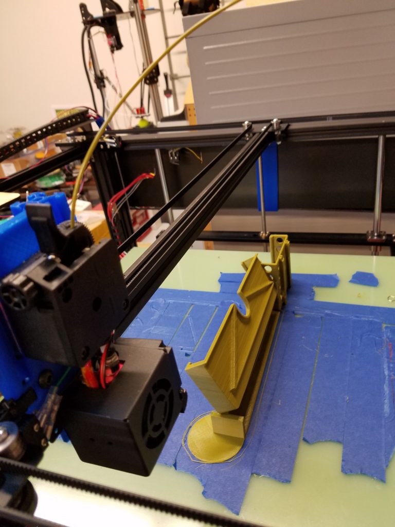
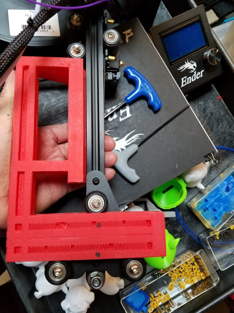
To make a long story short (See part three for the conclusion) an offset square was developed. It is a little tricky as the important relation is the line formed by the vertical rollers on the z-axis carriage and the extrusion beam that the extruder or X-axis carriage rides on. The mounting screws of the sheet metal pieces to the T-nuts on the extrusion can allow a considerable skew. The parallelism can be accommodated by adjusting the spring loaded tensioners on the heated bed. But once measurements were taken something seemed amiss. (See data analysis in part two.)

THE PUNCH LINE:

The square developed has a facsimile 20×40 rail with a 20×20 extension at the right offset to aid in assembling the roller plate and extrusion in a perpendicular relationship. Once TP was realigned, the next batch of parts looked extremely promising and we are awaiting the results quantitatively.

A special square assembly aid designed and 3D printed on an Ender3 for setting the proper relationship between the z-axis rollers and the X-axis beam.

Stay tuned for Part Two and Part Three where we analyze the data, describe the realignment procedure and test the results!!

3D Printing Projects 202002 – TUSH on TRON

Remixed TUSH rollers for TRONzilla. Outside fins to hold spool intact, clips for 40×40 extrusion, and 3 mm assembly screws with nut indent for wrench-less tightening.

The Ultimate Spool Holder (TUSH) was adapted for supporting the direct drive conversion of TRONzilla. The project started by printing a superstructure mounted on TRONzilla using the 40×40 extrusion profile (These large 40×40 sections were printed on TRONzilla). Clips were added to hold the roller assembly in place. The friction is enough so the top needs no teeth like the original TUSH. The rollers can be slid easily along the extrusion and the weight of the spool and friction of the clips keep them to the proper spacing. Screws were added to the bearing spindles to keep the halves together and made symmetrical with a hex indent to hold the nut so only a hex driver is required for tightening. The spool rolls so easily it was necessary to add larger flanges to the outside half to keep the spool on top of the rollers as it wanted to spin out of its cradle. The extrusion profile was imported in to SolidWorks and then using the sweep function developed in the bracket you see. The TUSH model was adapted with engagement fingers in to the grooves of the extrusion profile. The original TUSH has a flat gear for setting the spacing of the spool rims. By adding a captive nut pocket the bearings are trapped more securely with a 3mm screw and nut and then the TUSH can just be slid along the profile to adjust for differing spool spacing. The extrusions were sliced in Simplify3D and printed in PLA on TRONzilla. The TUSH components were sliced in Simplify3D and printed in PLA on “Groot”, an Ender3. 


3D Printing Projects 202001 – Backup Camera Mount

TRON getting in the act!

This project extends the phone holder that attaches to the air vent in the dash to include the wireless backup camera viewer. The part was designed in SolidWorks, sliced in Simplify3D and printed in PLA on TRONzilla. The pocket was a little tight so another version is in the works as well as maybe moving it a little more forward. Worked good on its maiden voyage on an 11 hour road trip.