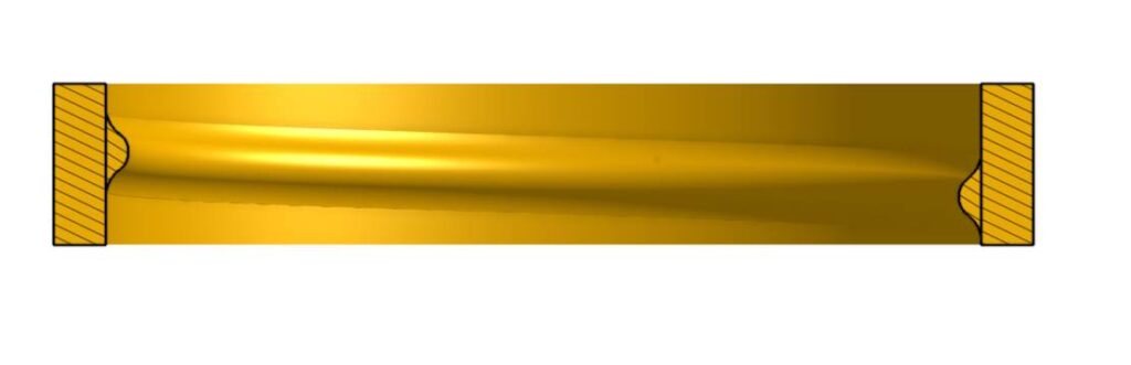
I wanted a simple but not trivial visual aid for the Onshape class and stumbled upon the 123 block as a nice prismatic practice piece. Pattering the holes got to be more involved than anyone imagined. Very good exercise for Oshape.
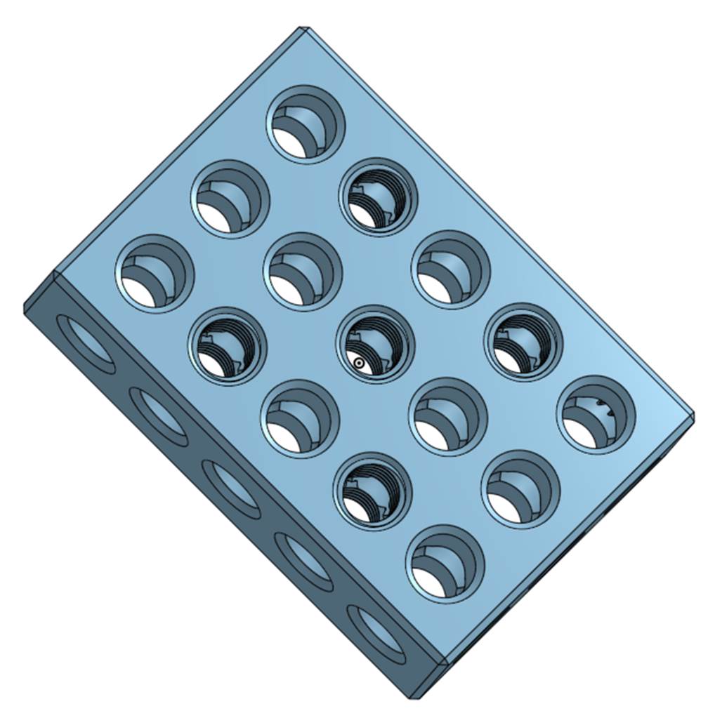
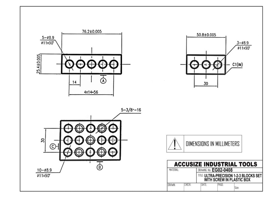
Utilizing an internet seach a drawing of a 123 block was found.
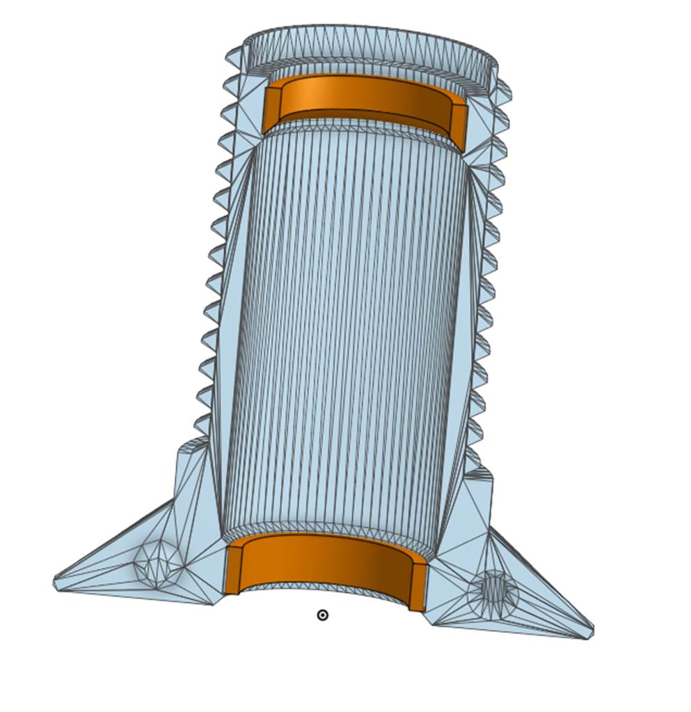
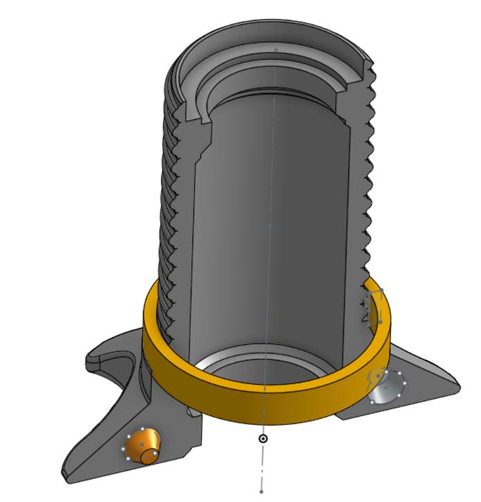
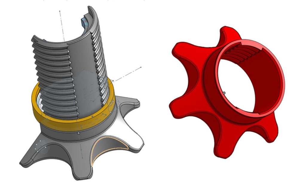
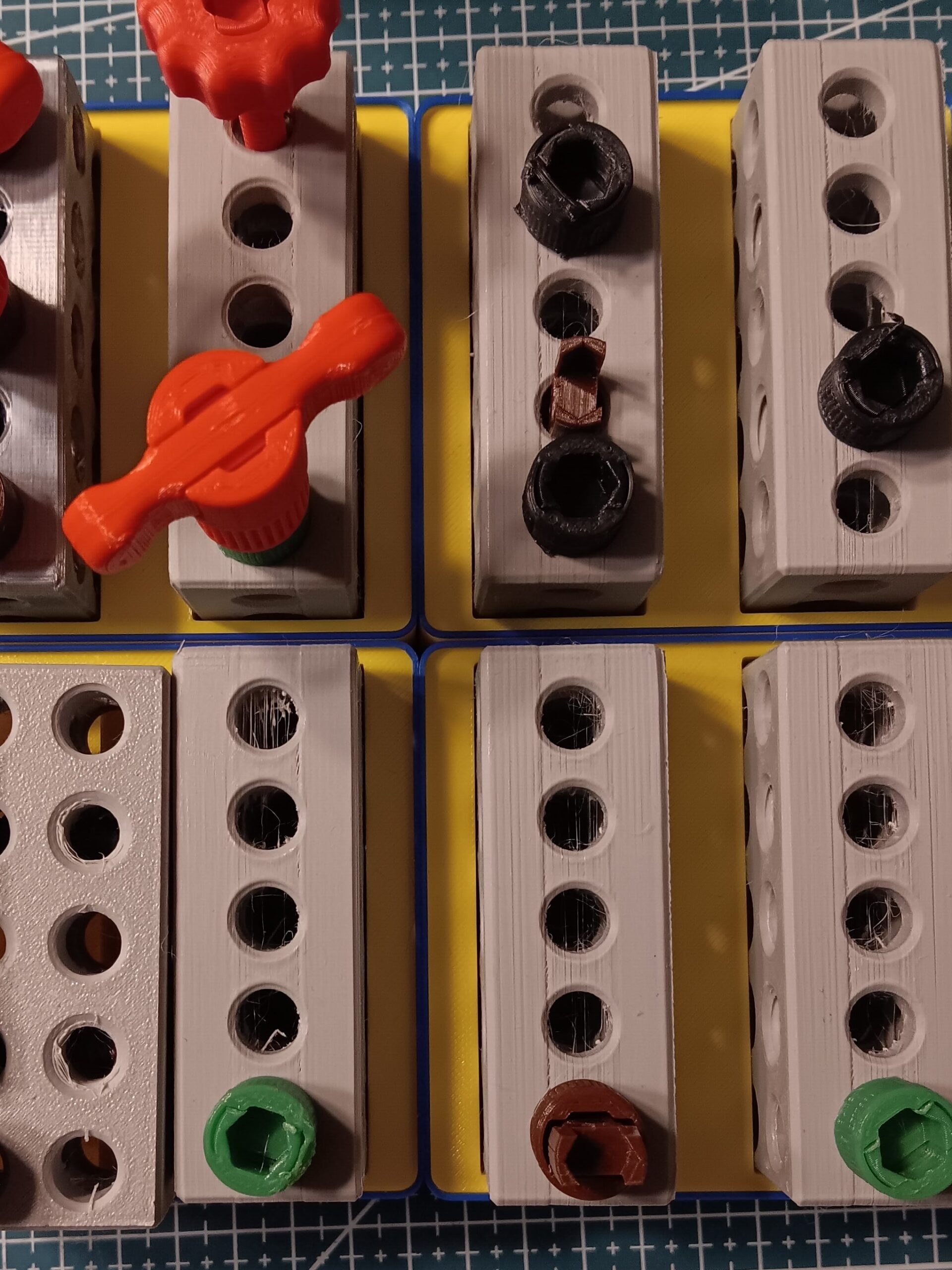
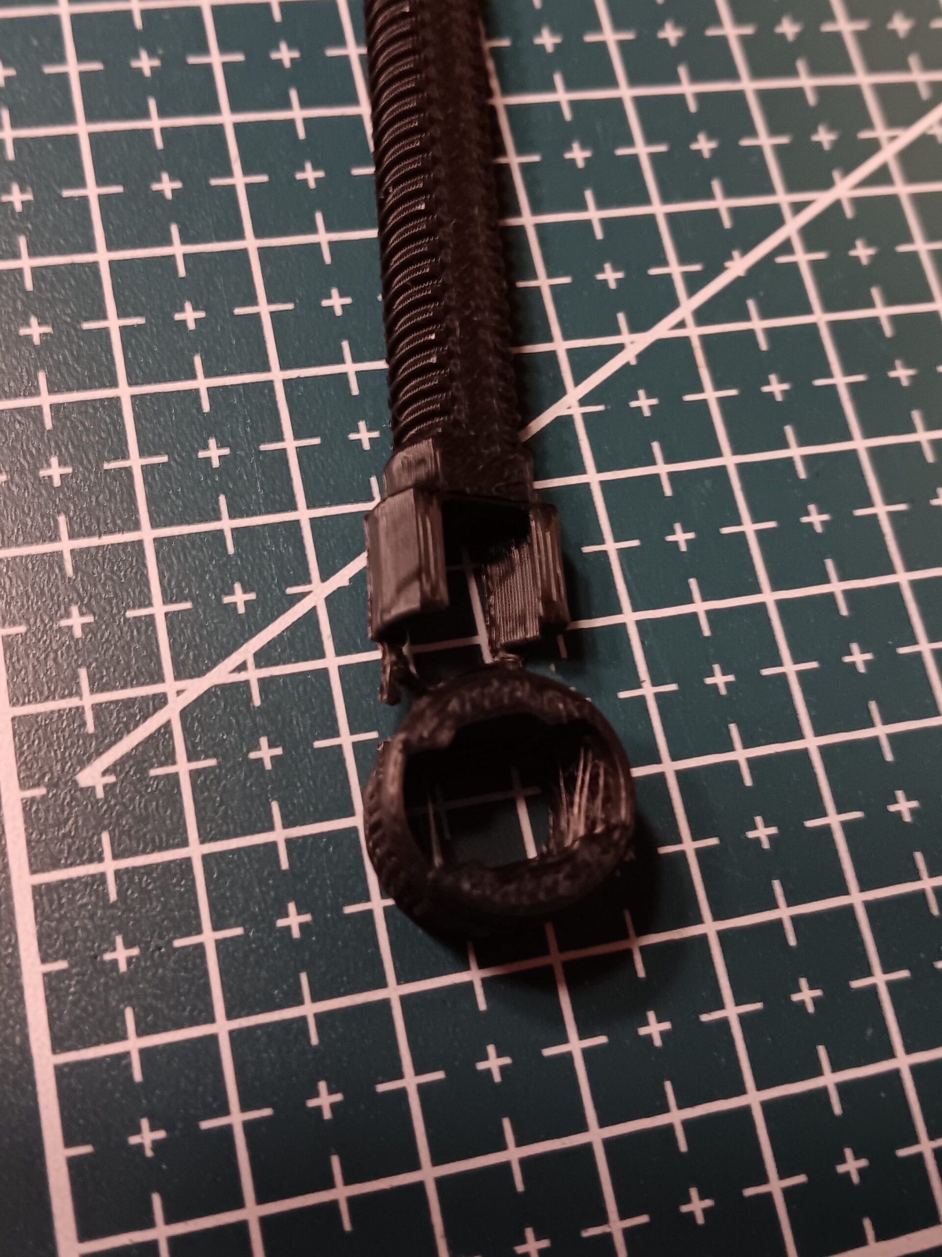
It would be nice to have fasteners to connect blocks together. To make stong threads the thread forms are printed in the XY orientation. The head was separated from the whole screw to form a T handle on the threaded portion and part of the hex socket for maximum torque. The head was then relocated for better printing orientation and a tree was added to hold them together until assembled. Configurations were established to make length selection easy.
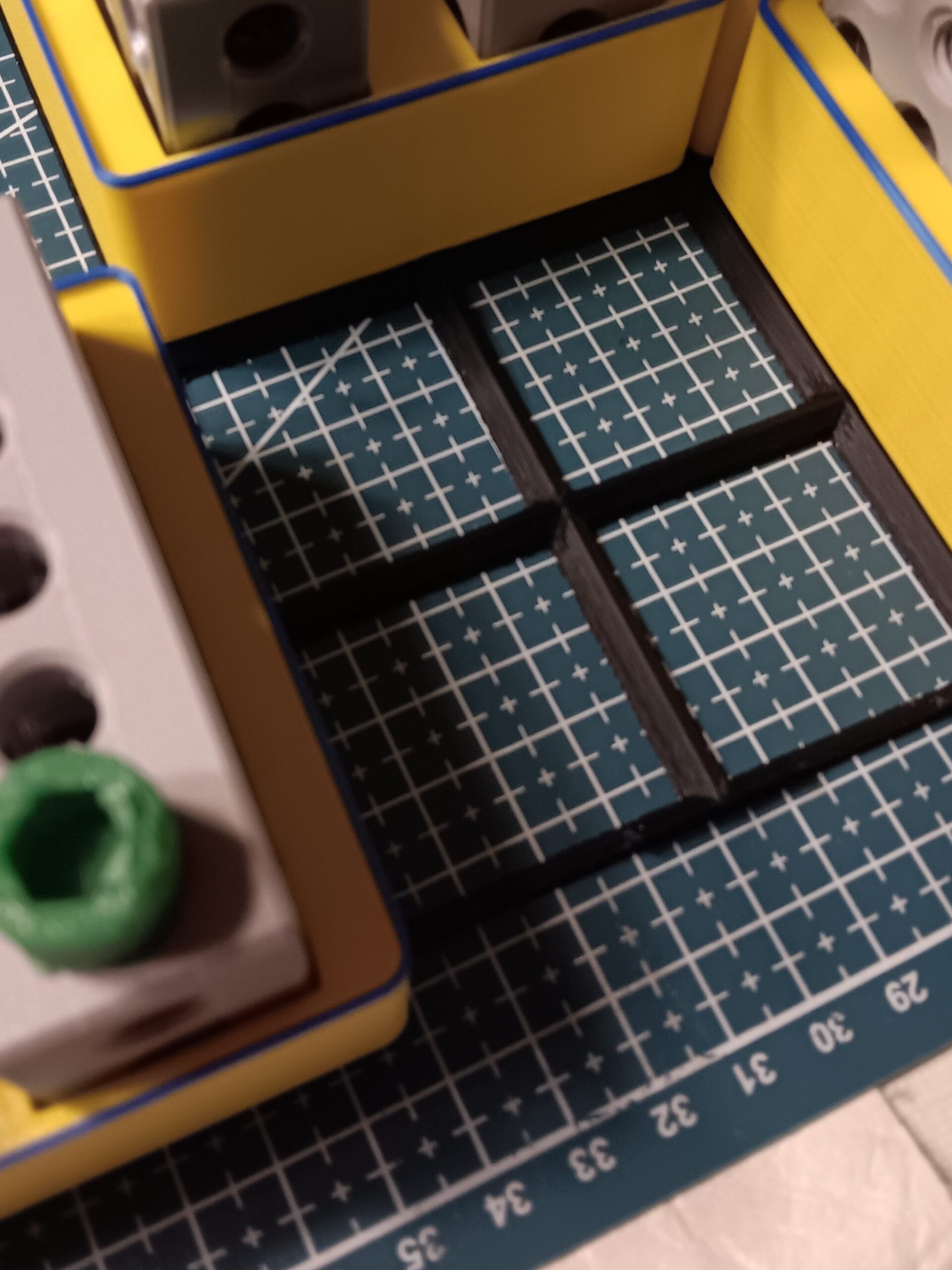
grid.
Parts were printed in PLA on the Ender3 V3 KE, Speedy-G and Tres (the 1st and 3rd refurbed KE in the lineup). The nests were printed in two color layers on the FF AD5X.Gridfinity base grids where printed on the Lost Cuz.