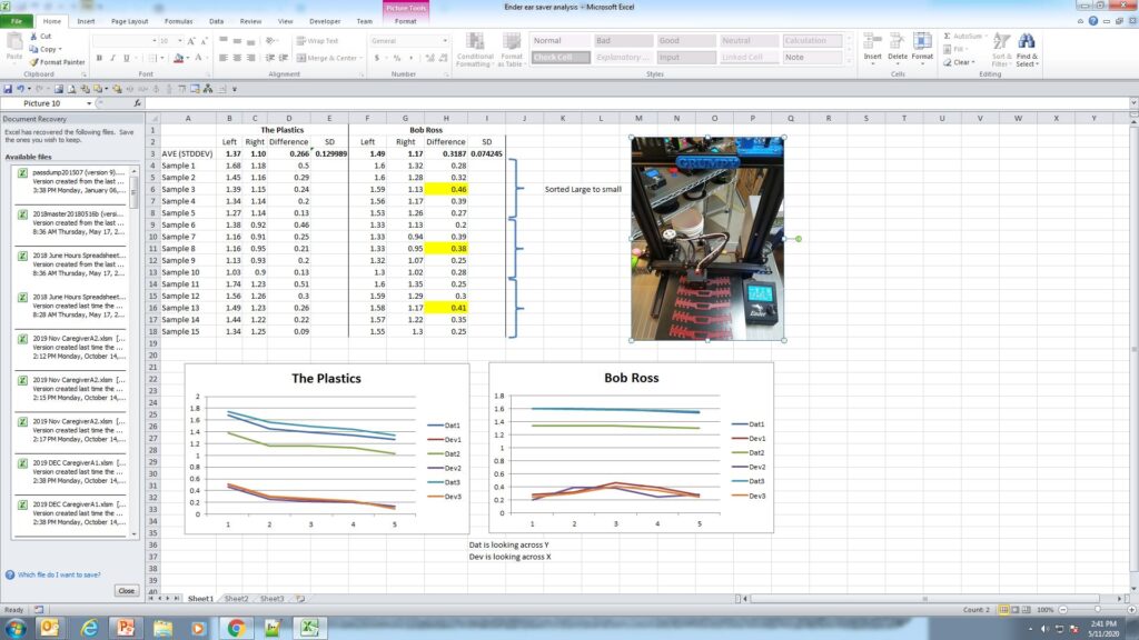
An infographic of sort identifying the data from 3 different part runs of 5 parts each for both Bob Ross and The Plastics Ender 3 printers. The picture identifies the orientation of the pieces on the build plate.
A Tale of two Ender 3’s…
“Bob Ross” and “The Plastics” (TP) both exhibited some strange printing behavior via the data. The clips were measured for depth on the left side and the right side. The deviation was calculated from the left side to the right side. The data was ordered in decreasing value of the 5 part run based on the left hand readings. (Note this is the side the Z-axis screw is mounted on the Ender 3.) Let’s examine these individually starting with Bob Ross.
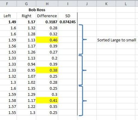
Data of 15 straps in batches of 5 on Bob Ross
It should be noted that the mask strap is a nominal 2 mm in height.
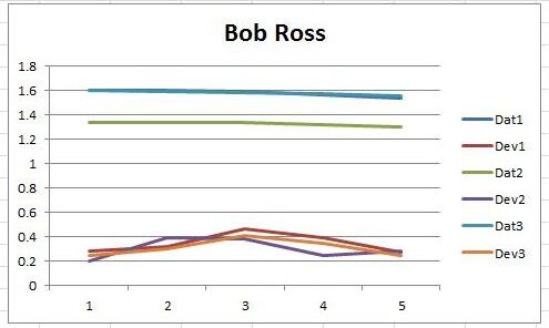
The measurements for each batch of 5 are listed. The data was sorted by decreasing value within each dataset. The deviation of depth was calculated from left to right. Two datasets were plotted for each batch. Dat is the left data and Dev is the difference data. The SD or Standard Deviation was calculated for all 15 differences. The average difference in all 15 is .31mm and the SD is 0.07. In the Ender 3 configuration the Dat values will represent the variation in the Y axis and the Dev values will represent variation in the X direction. Of interest is the small rise in data point #3 in each batch. As the data are not necessarily in order of placement on the machine it is difficult to surmise exactly the reason. In future measurements the order of placement will be noted.
Note the consistency of deviation in the Dat values on Bob Ross. Dat1 and Dat3 are nearly identical.
It should be also noted that Bob Ross and The Plastics both have aluminum plates and polymer covers for the build plate.
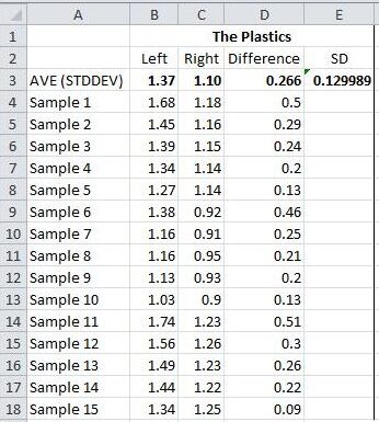
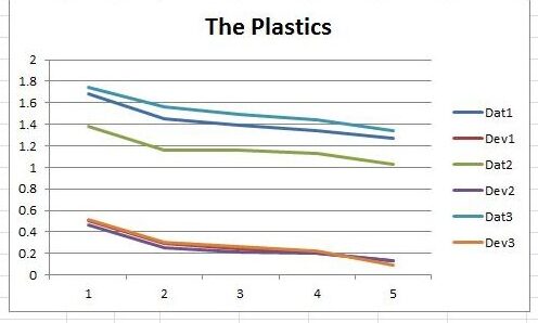
Data for 15 Mask Clips in batches of 5 from The Plastics Ender 3
The Plastics part runs exhibited repeatable trends with side to side deviations averaging less than those on Bob Ross. The standard deviation of the 15 parts was almost 50% greater however. The deviations are very consistent as shown in the graph with Dev1, Dev2, and Dev3 nearly colinear.
Interesting correlation on X and Y deviations on The Plastics Ender 3.
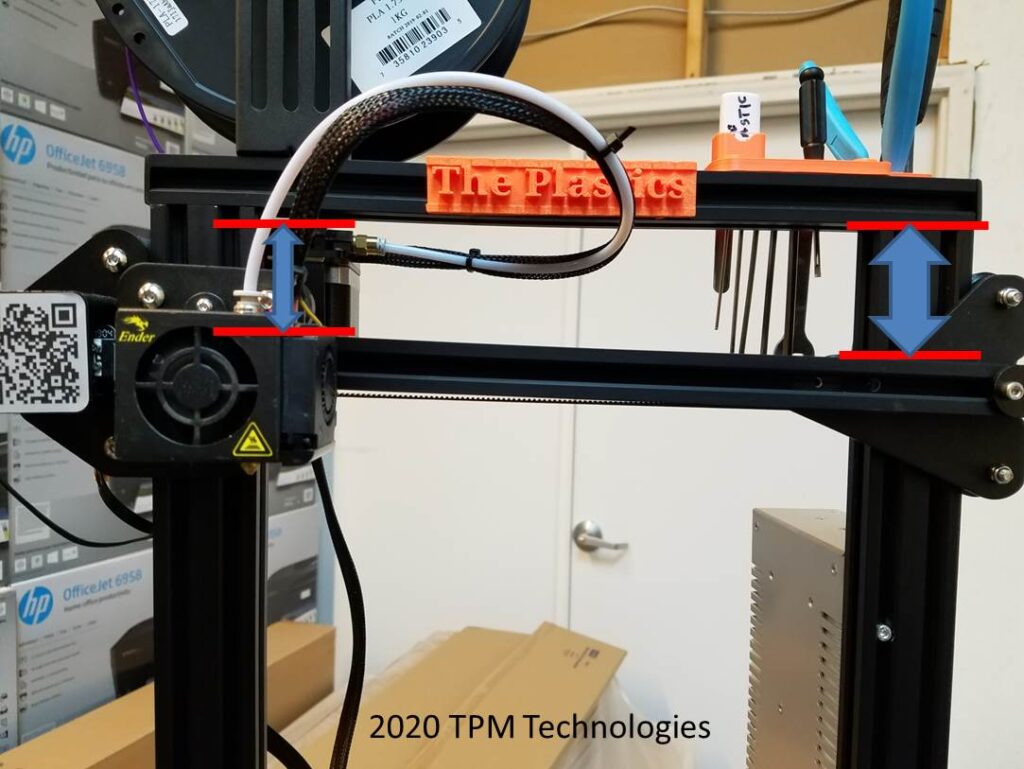
Besides just alignment the data shows something else must be happening. As the heated bed is spring loaded and the X axis is noticeably askew one can’t help but wonder if there is some multi-dimensional pressure at work.
Ender 3 TP had a skew on the X-axis rail. Conceivably the table was parallel to the rail via the alignment springs and screws.
THE SOLUTION:
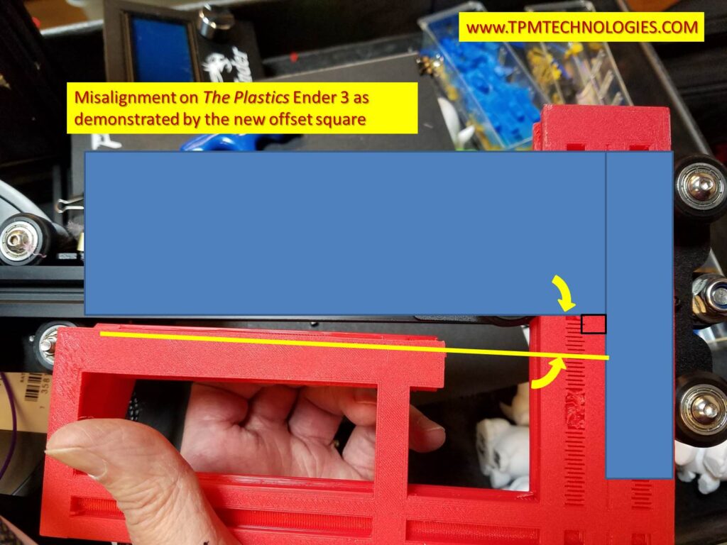
The fix was to develop a method for establishing a perpendicular or square relationship between the rollers on the z axis and the X-axis extrusion beam. The offset in the Y-dimension makes it difficult to use an ordinary square during assembly. To complicate matters the relationship that is critical is where the rollers form a line that needs to be perpendicular to the X-axis extrusion. The mounting screws of the sheet metal pieces to the T-nuts on the extrusion can allow a considerable skew.
Bob Ross Ender 3 printing the offset square.
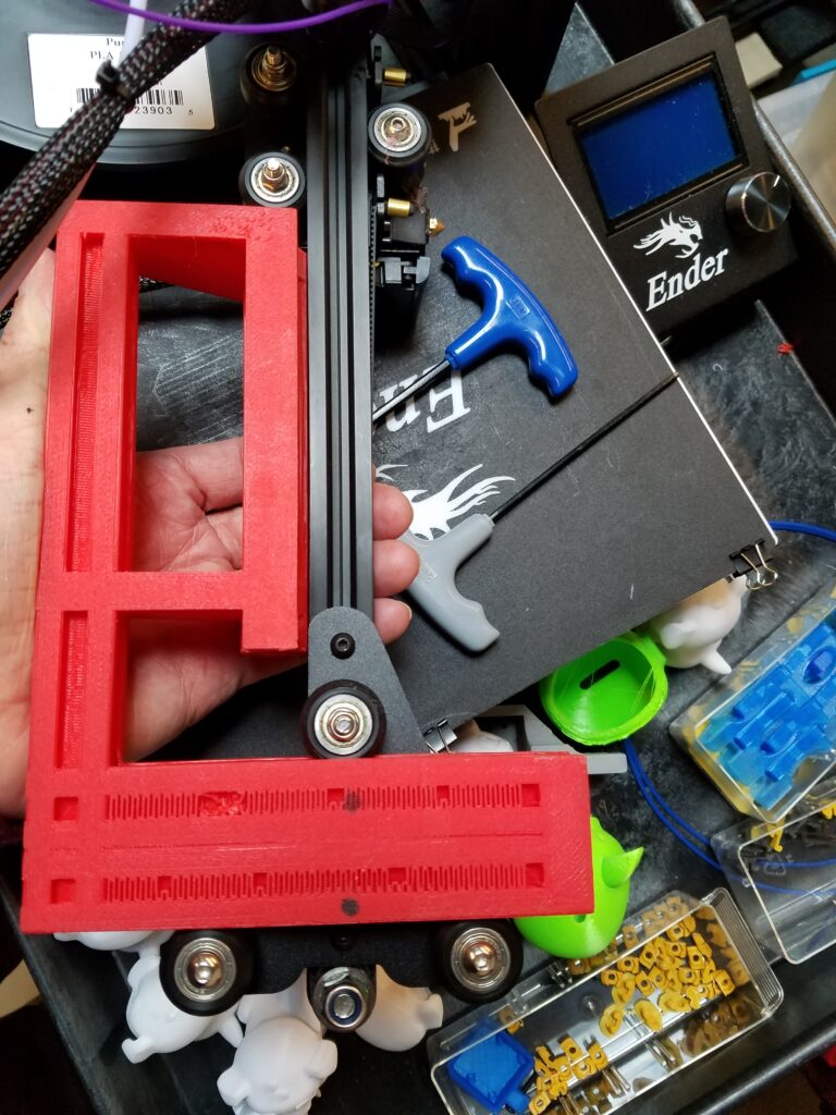
The square developed has a facsimile 20×40 rail with a 20×20 extension at the right offset to aid in assembling the roller plate and extrusion in a perpendicular relationship. The 20×40 section is inserted into the roller assembly to establish the roller line of travel. The printed 20×20 extrusion is mated to the X-axis extrusion beam to verify alignment. The fasteners can be loosened and the square used to establish the square relationship. See Part 3.
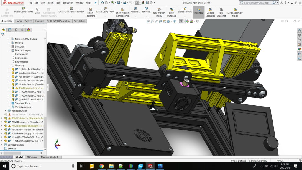
The Square was designed in SolidWorks leveraging models in the public domain for the extrusions. Luckily, someone had also made available the whole Ender 3 as an assembly so testing the fit of the design was relatively easy. In this figure you can see the offset square in both orientations to determine the squareness of both the X-axis motor mount (left side) and the belt take-up bracket (right side).The square is mirrored in the two applications to deal with the offset of the X-axis beam to the rollers. From the left the bottom of the extrusion is aligned and from the right the top of the extrusion is used.
The offset square shown in both orientations to align both the Ender 3 X-axis motor mount and idler bracket. Luckily someone had already developed a SolidWorks model so developing the square was relatively easy. In this view the vertical uprights are hidden and the square inserted and mated to the X-axis extrusion beam. Note the offset in the Y-direction to match up with the location of the extrusion.
THE FIRST TEST
The x-axis assembly is removed from The Plastics Ender 3 and the offset square inserted to review the alignment. OOPS.
The offset square was exported from SolidWorks, sliced in Simplify3D and printed on Bob Ross. The x-axis assembly was removed from The Plastics and the square used to see how far askew the idler bracket was. Stay tuned for Part Three where we describe the realignment procedure and test the results!!
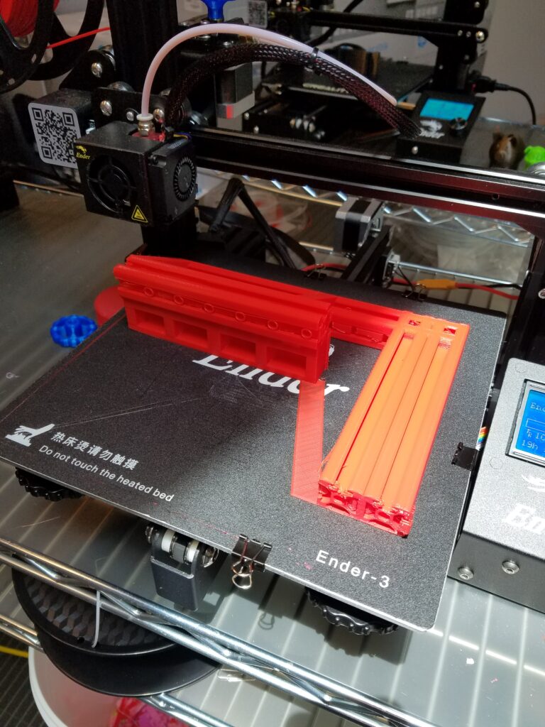
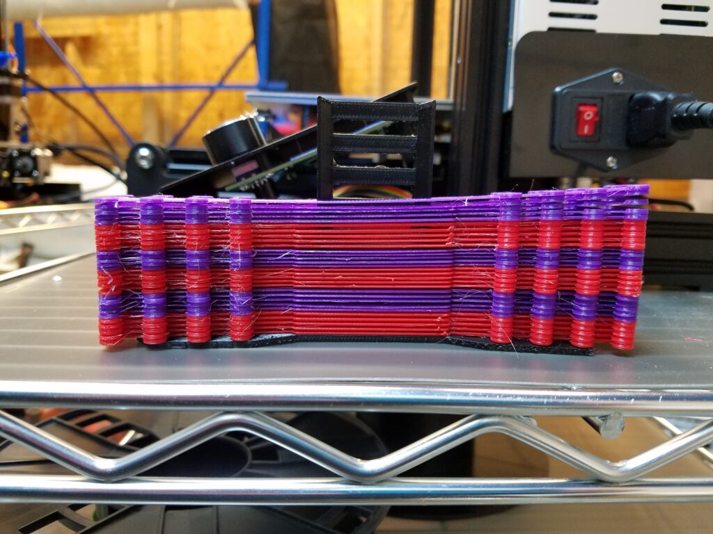
What’s wrong with this picture? Surgical mask clips stacked up show alignment issues on “The Plastics” Ender 3
A Tale of two Ender 3’s…
“Bob Ross” and “The Plastics” (TP) were printing surgical mask ‘ear saver’ clips. A friend wanted 40 of them for his audiologist friend as they found they were very helpful for not interfering with hearing aids when using masks. Upon further inspection with a caliper the clip on the right side of the machine (opposite of the Z axis screw) was considerably smaller than the left. Also, in a batch of 5 some variation was exhibited front to back.
In the picture, Bob Ross was printing red and TP was printing purple. Bob Ross fared better but still there was some variation. See part two for details. The X-axis beam on TP was noticeably oblique to the frame.
Ender 3 TP had a skew on the X-axis rail. Conceivably the table was parallel to the rail via the alignment springs and screws.
To make a long story short (See part three for the conclusion) an offset square was developed. It is a little tricky as the important relation is the line formed by the vertical rollers on the z-axis carriage and the extrusion beam that the extruder or X-axis carriage rides on. The mounting screws of the sheet metal pieces to the T-nuts on the extrusion can allow a considerable skew. The parallelism can be accommodated by adjusting the spring loaded tensioners on the heated bed. But once measurements were taken something seemed amiss. (See data analysis in part two.)
THE PUNCH LINE:
The square developed has a facsimile 20×40 rail with a 20×20 extension at the right offset to aid in assembling the roller plate and extrusion in a perpendicular relationship. Once TP was realigned, the next batch of parts looked extremely promising and we are awaiting the results quantitatively.
A special square assembly aid designed and 3D printed on an Ender3 for setting the proper relationship between the z-axis rollers and the X-axis beam.
Stay tuned for Part Two and Part Three where we analyze the data, describe the realignment procedure and test the results!!
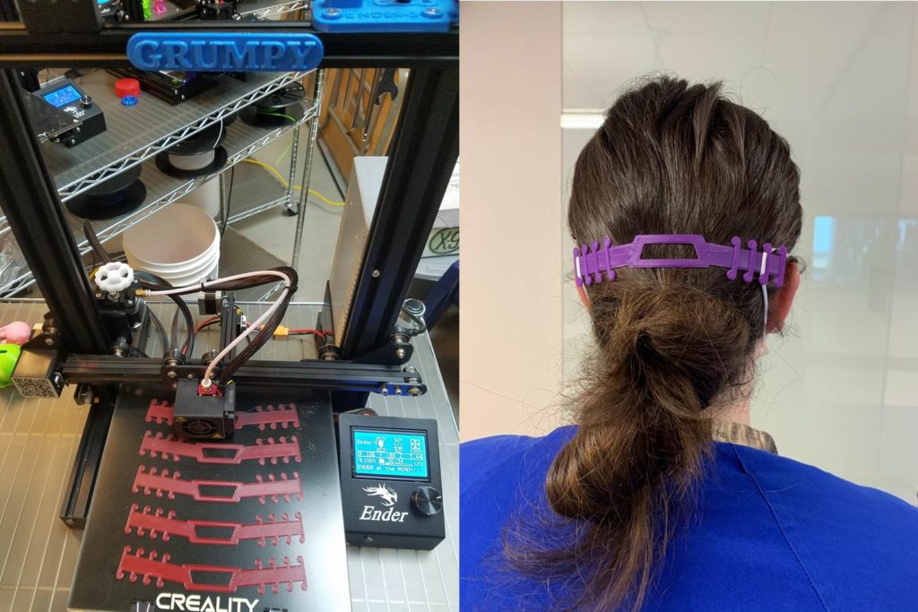
Grumpy showing off the recently installed glass plate. Healthcare worker demonstrates comfort and better fitting system for masks.
THE STORY
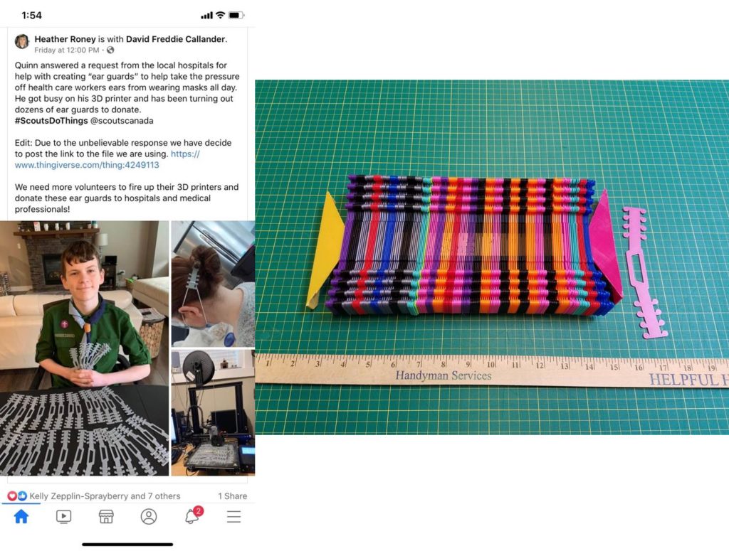
Healthcare workers ran across this article on Facebook and inquired about the possibility of printing them locally. Finding the file on Thingiverse and after a quick test print on “Groot” the go ahead was given for 150 copies. The nine Ender3’s were called into action printing 5-up at a time to crank out 200 in the space of a couple of days. PLA was used in multiple colors. A yardstick was recycled and 3D printed end pieces in ABS made it easy to keep track of production by counting the color bands. A single lime green strap marked the 100 position.
The inspiring Facebook article and the resulting initial lot of 150.
THE REST OF THE STORY
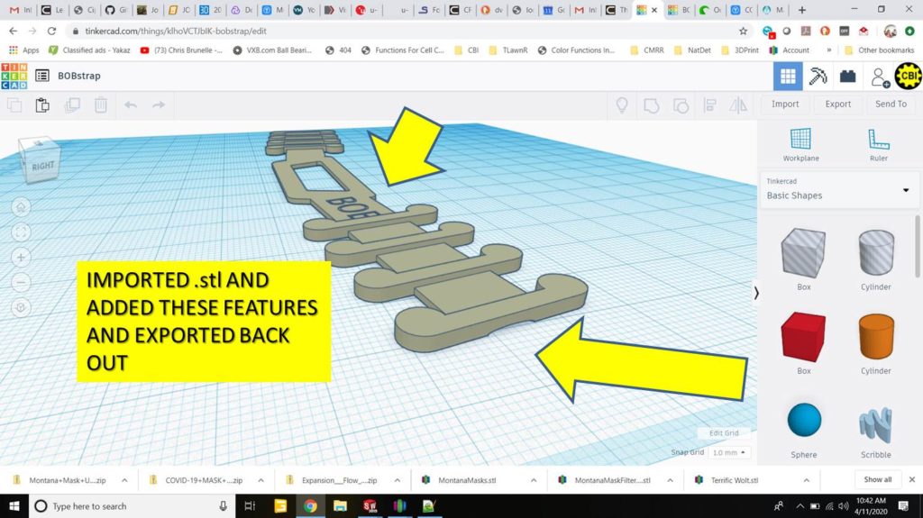
After removing so many clips from both glass plates and polymer skins some embellishments were conceived. TinkerCAD to the rescue. A name was embossed as well as a little dent in the bottom surface for easy removal.The tweaks were then exported and re-sliced in Simplify3D.
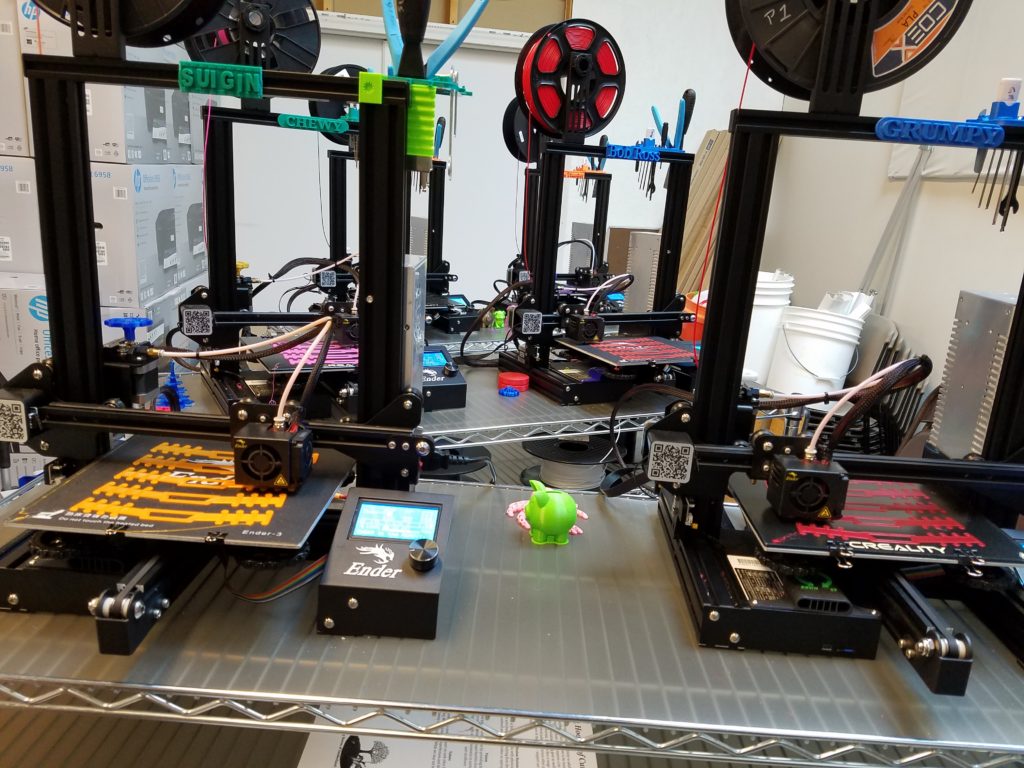
Here’s a shot of the Ender3 “Printer Farm” in action.
Ender3’s busy printing Surgical Mask Clips in TN, Suigin, Grumpy, Chewy, Bob Ross, Rocket, The Plastics. Groot, Kermit, and Ms. Kiesha not in this photo.
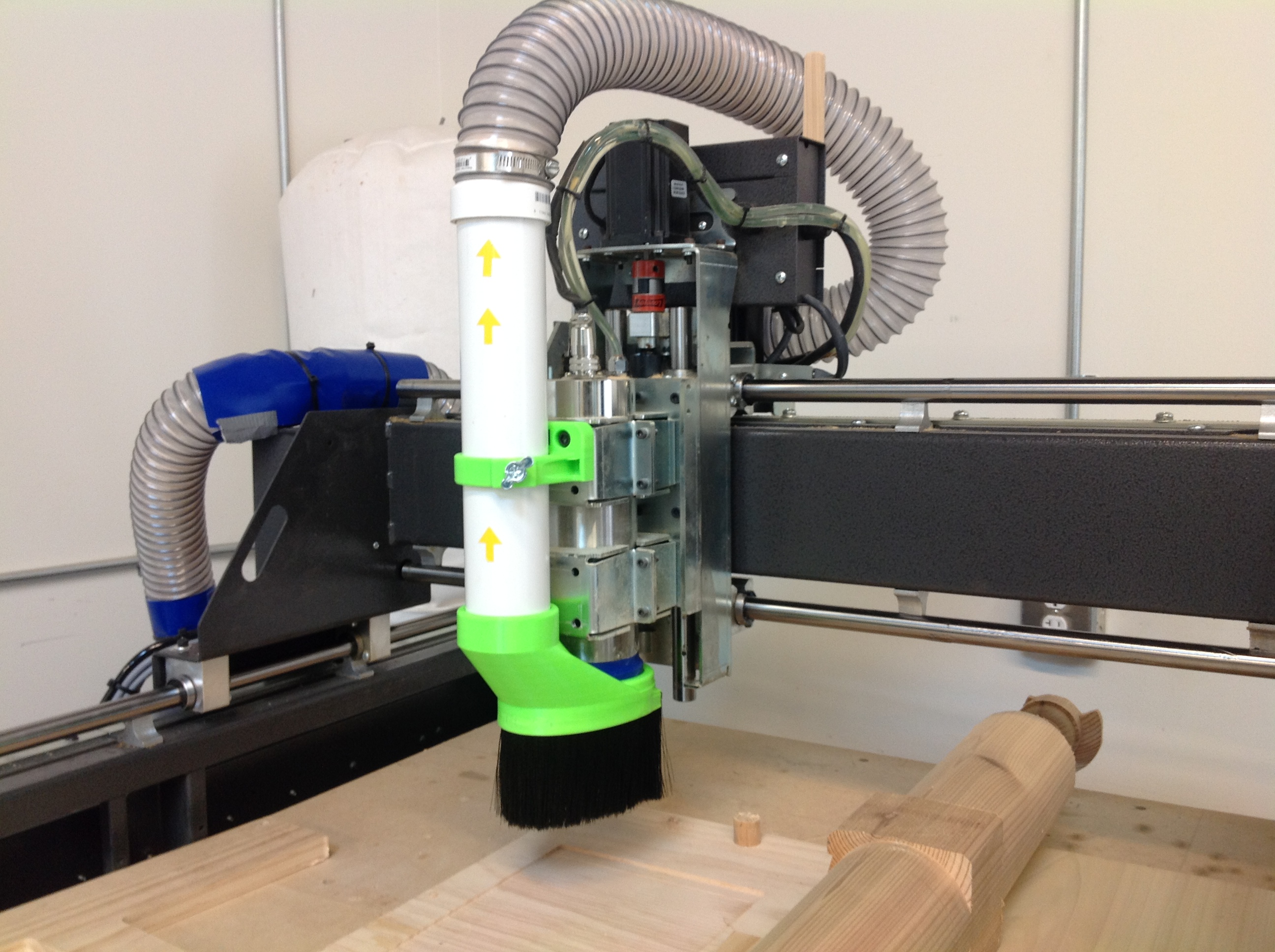
Having an effective dust collection system for a CNC router keeps the area clean and chips don’t get a change to foul up the cutting. Pipe and snout pieces were designed in SolidWorks and printed in ABS. The primary nozzle has a T-slot where a flexible brush can be inserted. The system keeps the work surface tremendously clean. Parts were printed on FlashForge Creator and Creator Pro.
Biki is a tweaked design based on O.T. Vinta’s Rubiks Cube solving robot. All constructed of 3D printed ABS minus some fasteners and motors. A significant change from the original was to make the legs in 3 pieces with print orientations to maximize the strength of the various parts. The carrying handle was also not part of the original design. The embossed embellishments were created in SolidWorks. Simplify3D was used to drive various build files for the FlashForge Creator and Rostock Max.
Bob the woodworker has a special flexible brush for spreading glue but it couldn’t reach in the crack of a biscuit slot. We developed a two filament print using Tough Ink filament for the bristles and ABS for the handle. The bristles are about 1/8 inch wide and fit easily in the biscuit groove.The design was done using SolidWorks and Simplify3D makes the work flow of two headed printing streamlined. The part was printed on the FlashForge Creator.
A friend was interested in a Dinosaur bank. We found a Brontosaurus on Thingiverse. The body was hollowed out in Meshmixer and a coin slot was added. The unit was scaled and sliced with Simplify3D. This was a two tone version just to add some variety. The part was printed on the FlashForge Creator in ABS.
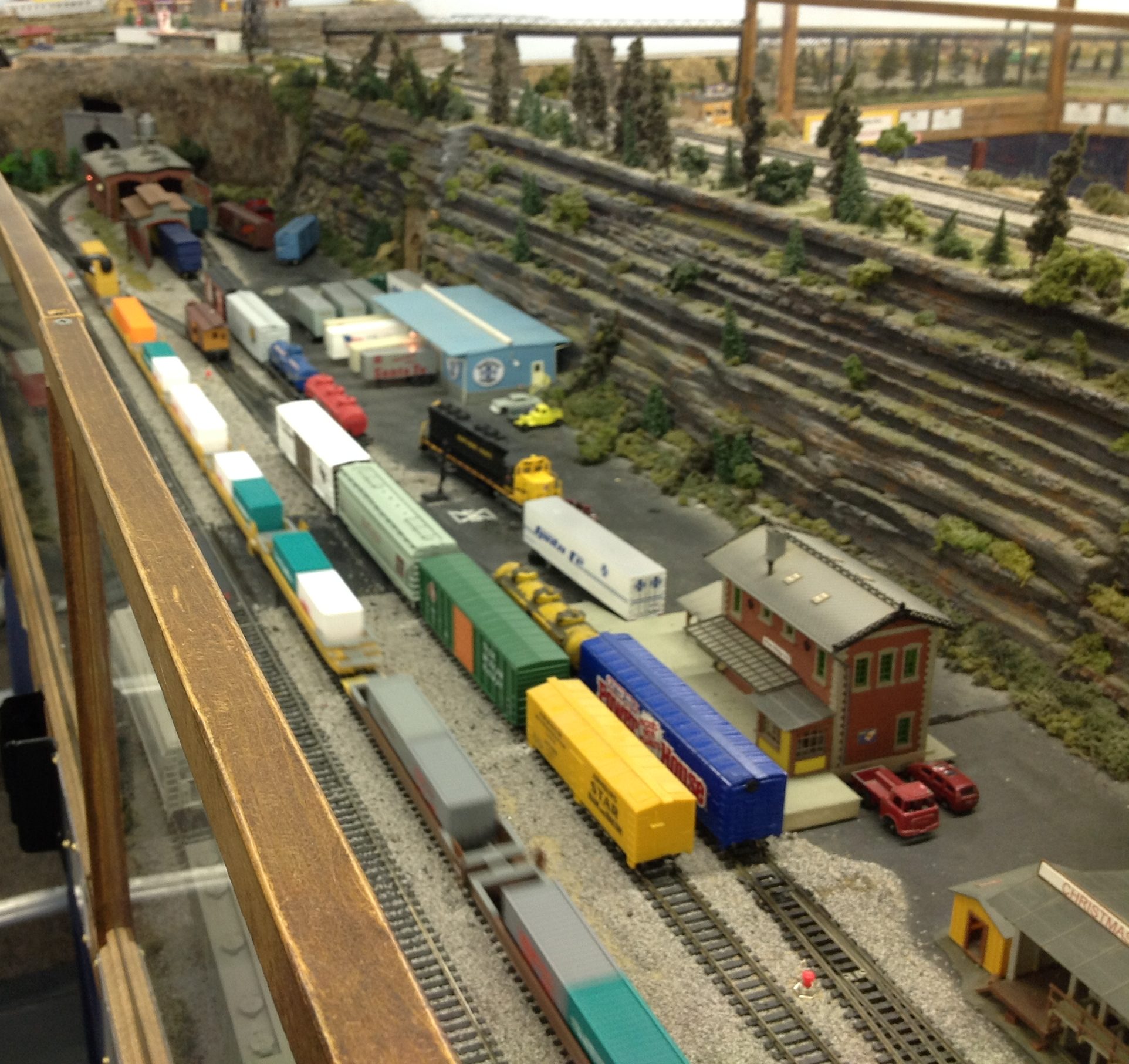
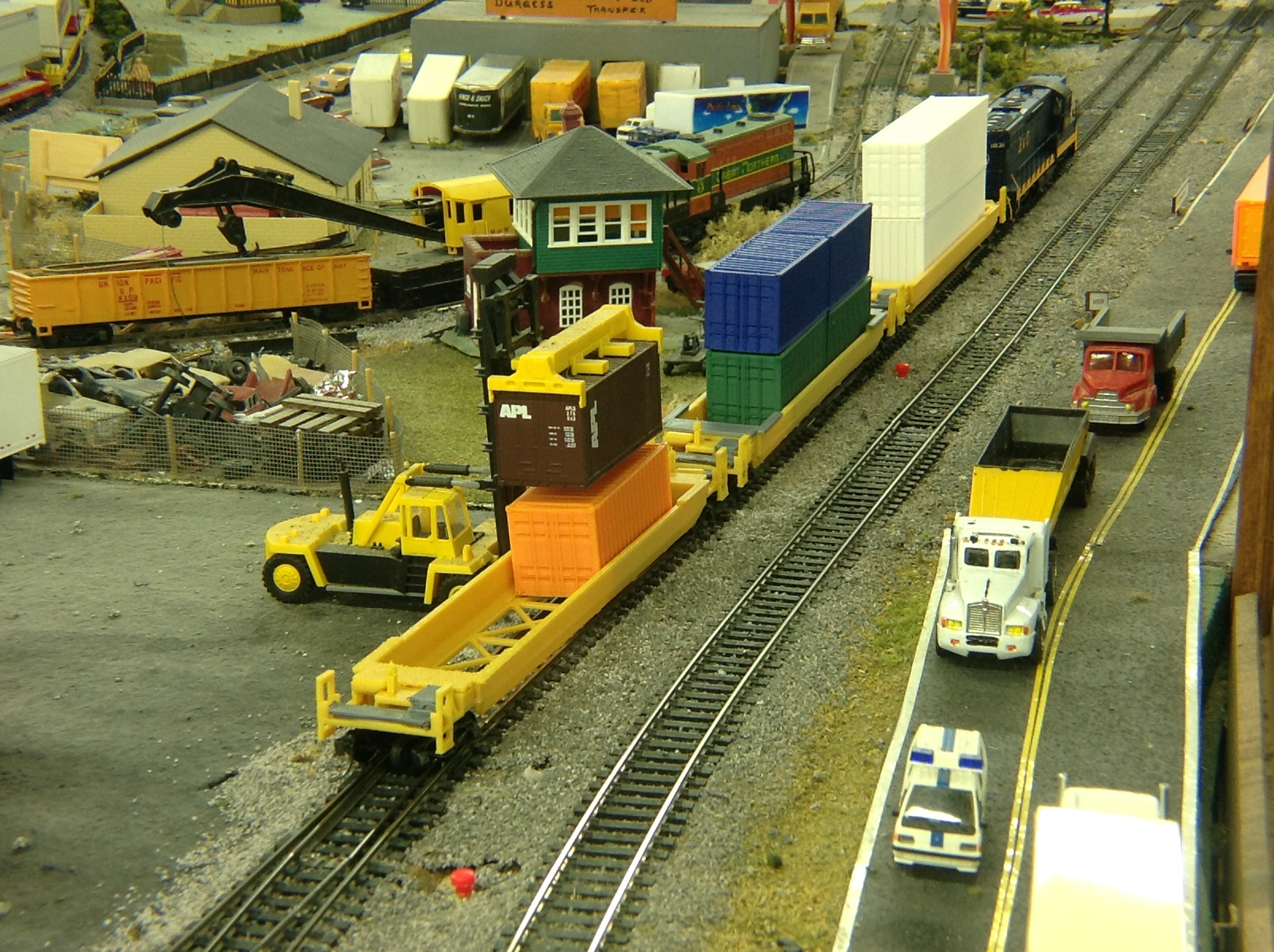
The lineup of four, 5-gang well cars and containers all 3D printed.
TPM Technologies had the opportunity to present 3D printing applications to model railroaders at a regional convention. The application chosen was containers and wellcars. Every car and containers starting with the 4th car are 3D printed.
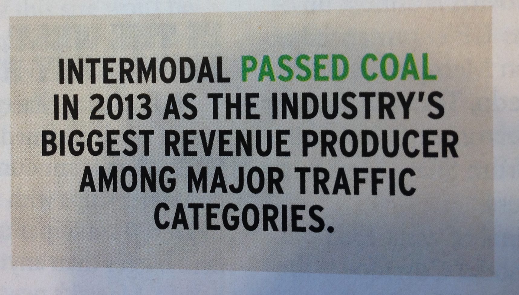
Why containers and well cars?
The design was developed in SolidWorks and the majority of the parts were printed on the FlashForge Creator, “Cat’s Paw”.
Here’s is a close up of some of the cars in the railroad club’s layout.
Well cars on the mainline zipping by boxcars on the siding.
Checking out container loading on the well cars with the forklift.
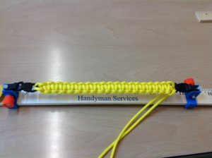
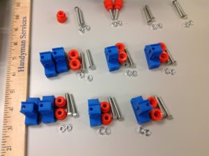
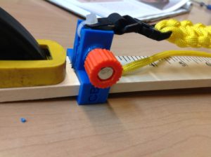
At a summer Make Camp we wanted an inexpensive way for the campers to jig up bracelets and other paracord weavings. A clamp for each end was devised that straddled a yard stick for easy sizing. With a trapped screw and nut the ends are easily adjustable to the right point on the yardstick.
The design was developed in SolidWorks and the parts were printed on the Makerbot Replicator in ABS.
 Having an effective dust collection system for a CNC router keeps the area clean and chips don’t get a change to foul up the cutting. Pipe and snout pieces were designed in SolidWorks and printed in ABS. The primary nozzle has a T-slot where a flexible brush can be inserted. The system keeps the work surface tremendously clean. Parts were printed on FlashForge Creator and Creator Pro.
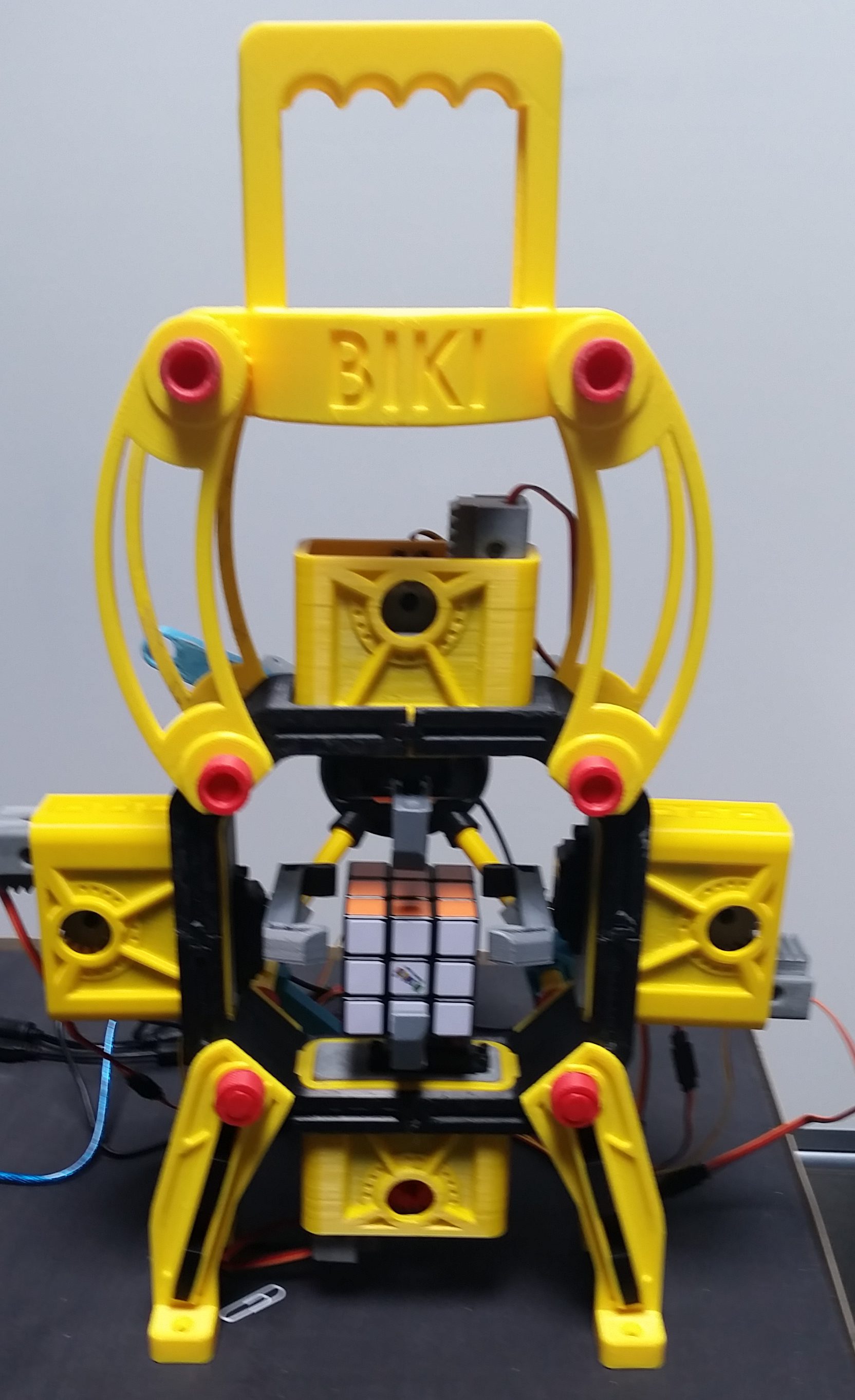 Biki is a tweaked design based on O.T. Vinta’s Rubiks Cube solving robot. All constructed of 3D printed ABS minus some fasteners and motors. A significant change from the original was to make the legs in 3 pieces with print orientations to maximize the strength of the various parts. The carrying handle was also not part of the original design. The embossed embellishments were created in SolidWorks. Simplify3D was used to drive various build files for the FlashForge Creator and Rostock Max.
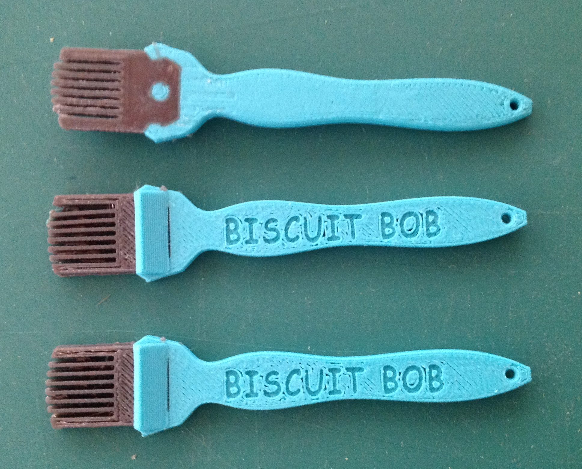 Bob the woodworker has a special flexible brush for spreading glue but it couldn’t reach in the crack of a biscuit slot. We developed a two filament print using Tough Ink filament for the bristles and ABS for the handle. The bristles are about 1/8 inch wide and fit easily in the biscuit groove.The design was done using SolidWorks and Simplify3D makes the work flow of two headed printing streamlined. The part was printed on the FlashForge Creator.
 A friend was interested in a Dinosaur bank. We found a Brontosaurus on Thingiverse. The body was hollowed out in Meshmixer and a coin slot was added. The unit was scaled and sliced with Simplify3D. This was a two tone version just to add some variety. The part was printed on the FlashForge Creator in ABS.
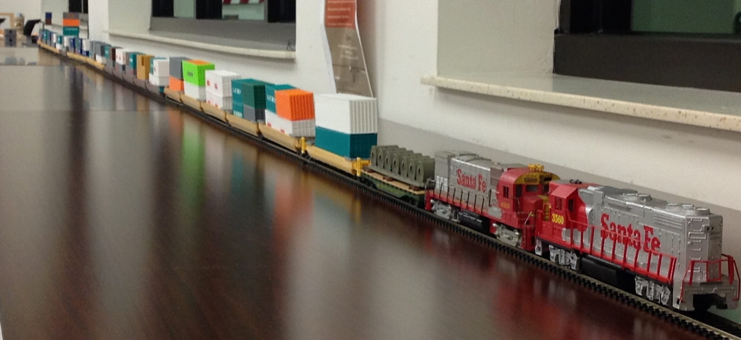
 At a summer Make Camp we wanted an inexpensive way for the campers to jig up bracelets and other paracord weavings. A clamp for each end was devised that straddled a yard stick for easy sizing. With a trapped screw and nut the ends are easily adjustable to the right point on the yardstick.