3D Printing Projects 201501 – HO scale wellcars and containers

IMG_7429

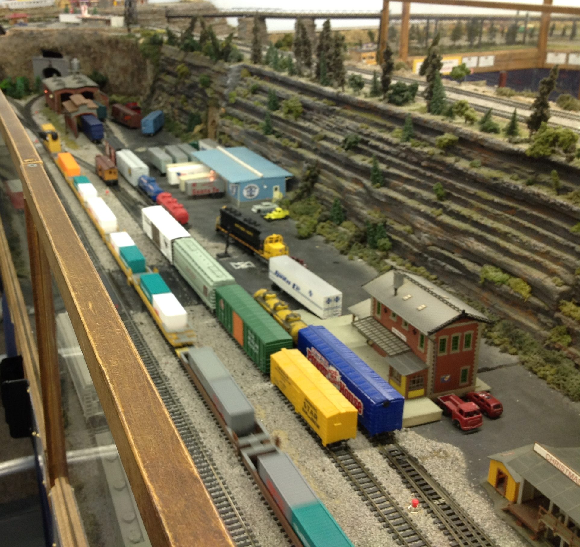
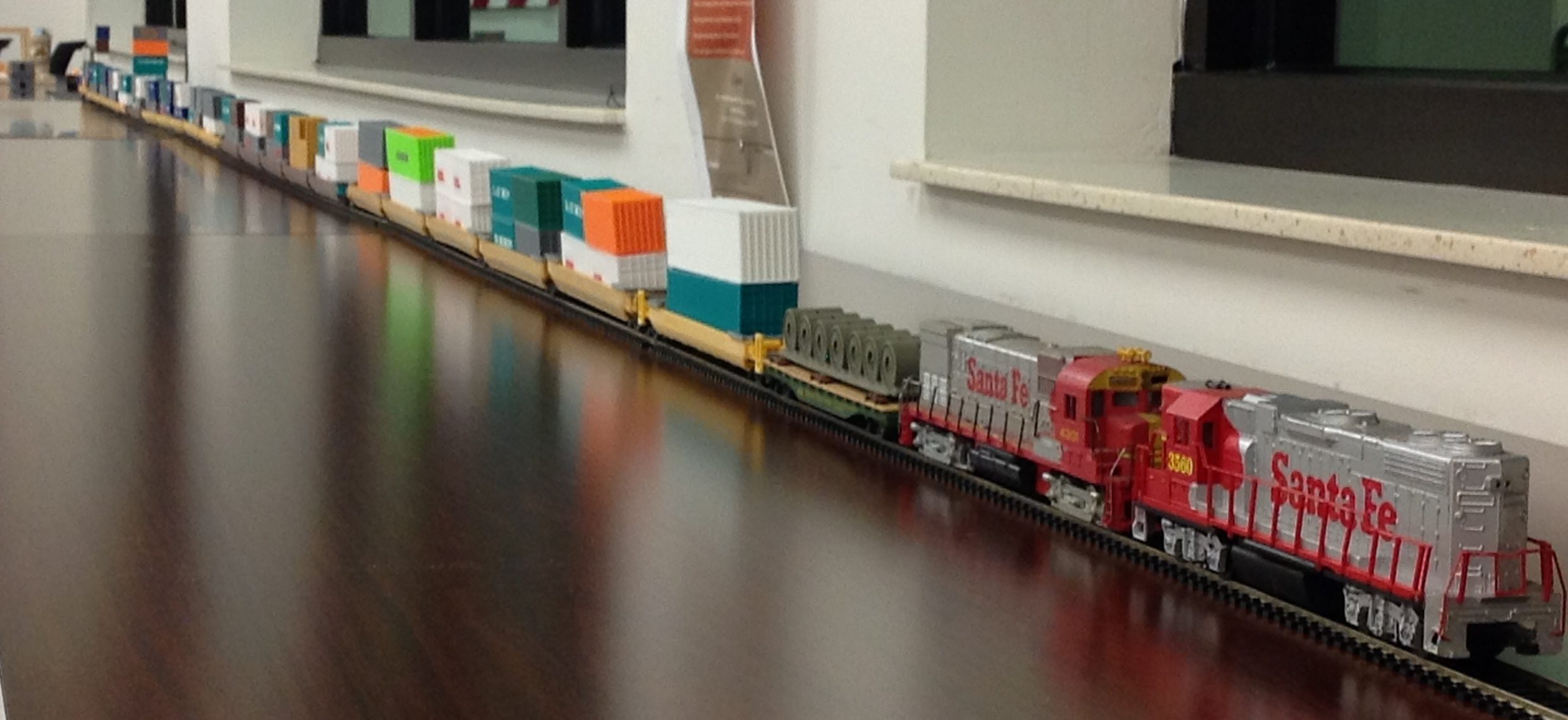
The lineup of four, 5-gang well cars and containers all 3D printed.

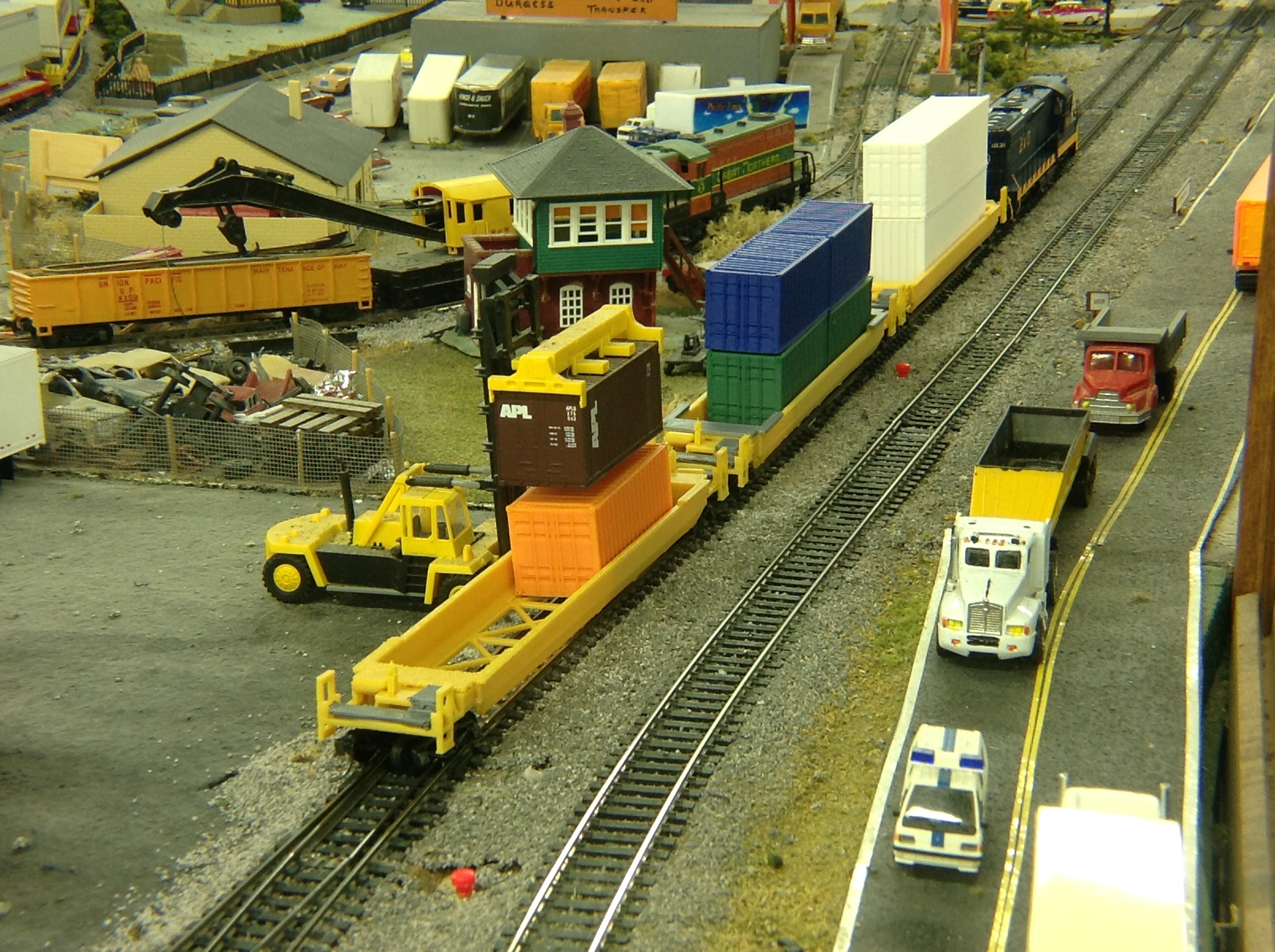
TPM Technologies had the opportunity to present 3D printing applications to model railroaders at a regional convention. The application chosen was containers and wellcars. Every car and containers starting with the 4th car are 3D printed.

Why containers and well cars?

IMG_7384

The design was developed in SolidWorks and the majority of the parts were printed on the FlashForge Creator, “Cat’s Paw”.

Here’s is a close up of some of the cars in the railroad club’s layout.

IMG_7454

Well cars on the mainline zipping by boxcars on the siding.

IMG_7122

Checking out container loading on the well cars with the forklift.

3D Printing Projects 201601 – Paracord jig with a yard stick and 3D printed parts

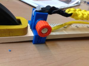
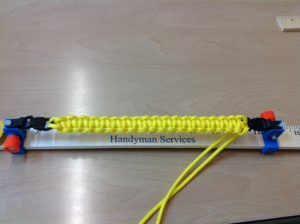
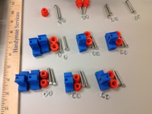
IMG_3372At a summer Make Camp we wanted an inexpensive way for the campers to jig up bracelets and other paracord weavings. A clamp for each end was devised that straddled a yard stick for easy sizing. With a trapped screw and nut the ends are easily adjustable to the right point on the yardstick.

The design was developed in SolidWorks and the parts were printed on the Makerbot Replicator in ABS.

IMG_3373


IMG_3381


3D Printing Projects 201502 – Rostock MAX tool-less home adjust cheapskate plates

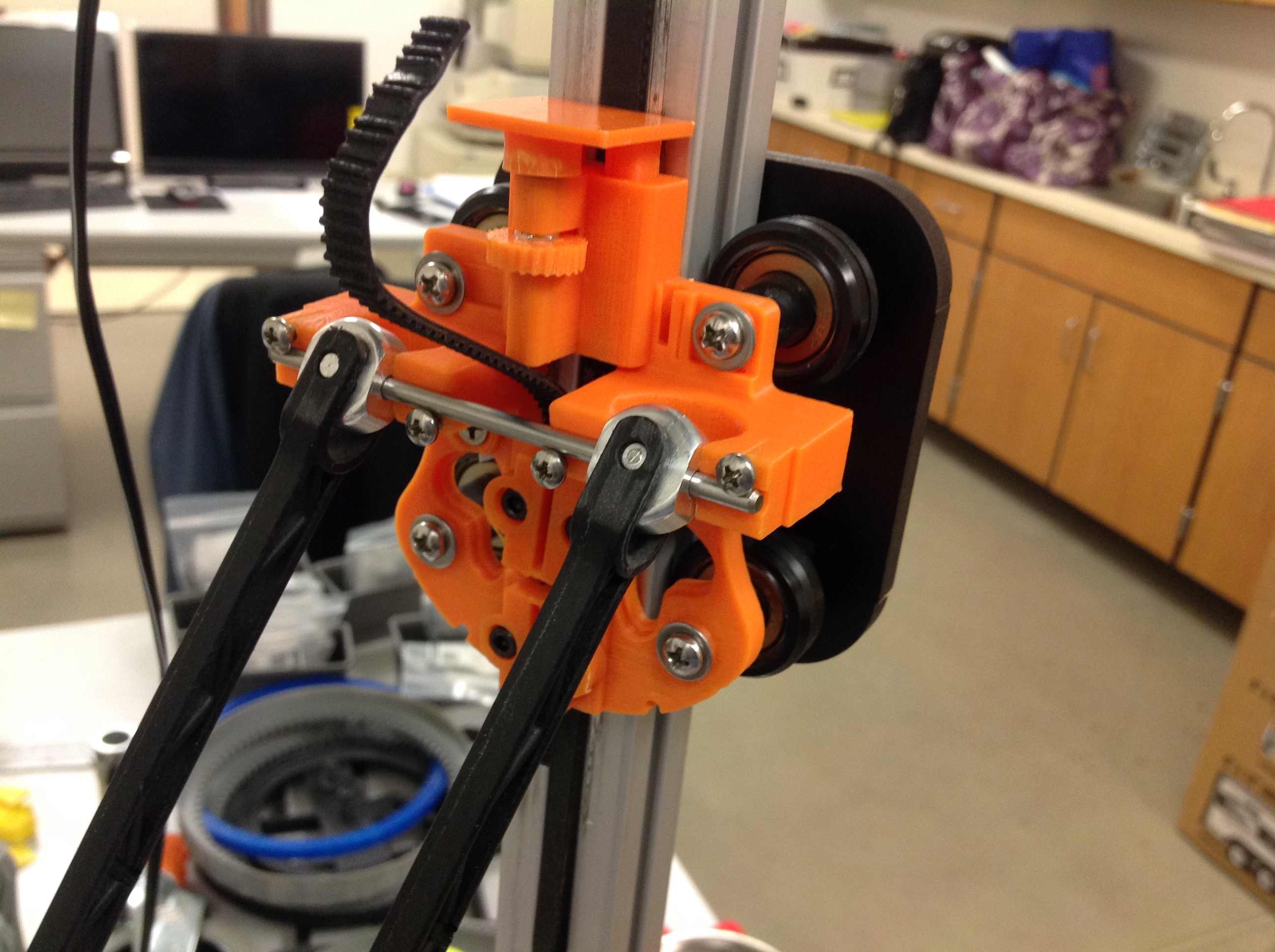
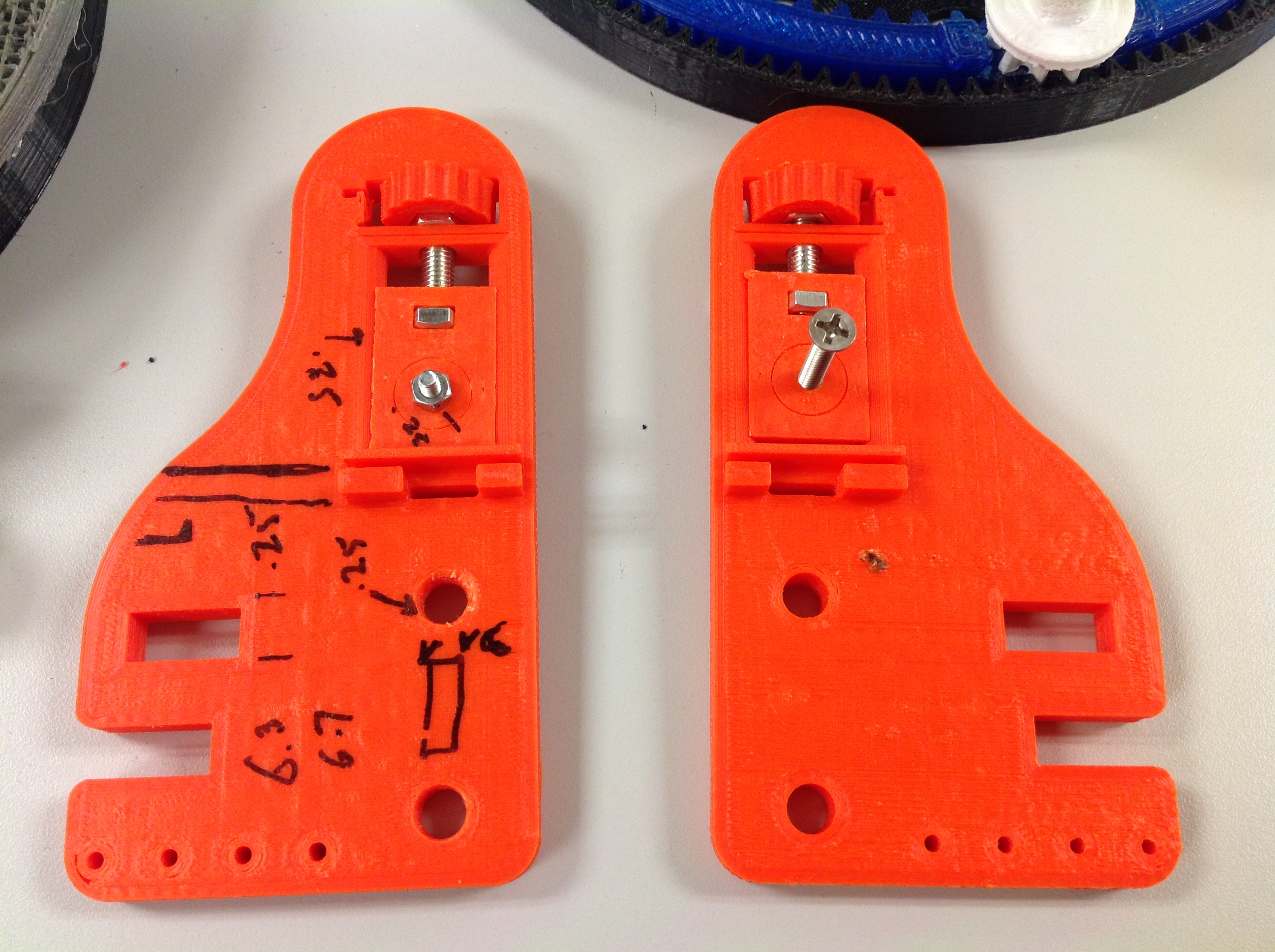
IMG_5344The original home switch dog on the Rostock Max was a long screw that wobbled and interfered with the other pieces and didn’t consistently engage the limit switch. You need a screwdriver to tweak it. We replaced it with a nice engaging, consistent ledge. While we were at it we redesigned the whole cheap skate bearing block into a “banjo” complete with toothed belt clamps. The number of parts was significantly reduced as well. The best part is no tools are required to adjust the home dog location. A screw is used as a micro-adjust and the nut is trapped in a knob. The ribs of the knob are held in place with a spring printed in the housing.

The ‘banjo’ was designed in SolidWorks and printed in ABS on the Makerbot Replicator. Each axis is color-coded to match the belt tensioners. In this version the screws enter from the inside making the tightening clumsy as your screwdriver interferes with the rods and extruder. In a later design version the ‘banjo’ is modified to trap the nut in a hex socket and tightening is accomplished from the outside with no interference.

3D Printing Projects 201501 – Rostock MAX tool-less belt tensioner plates

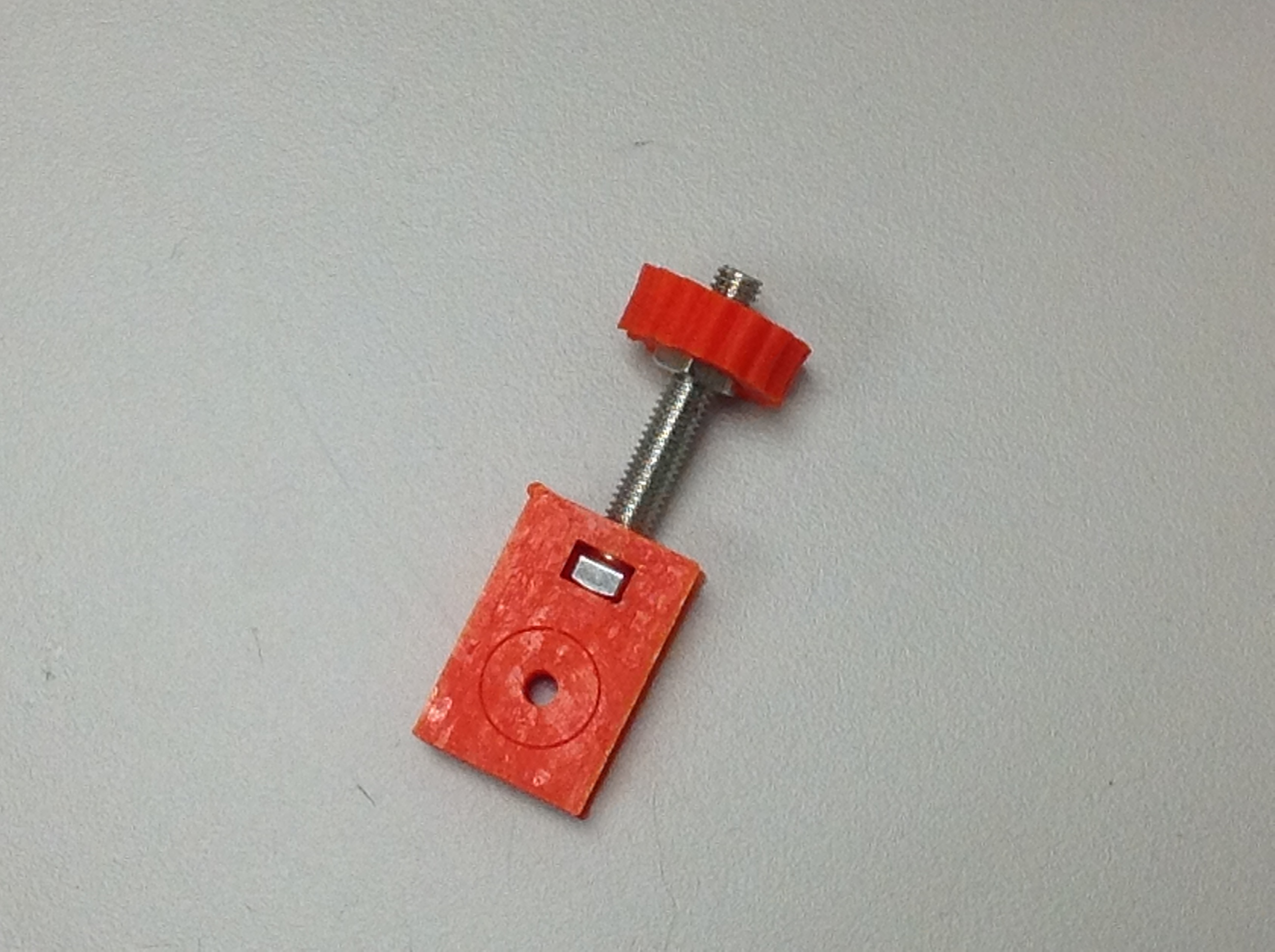
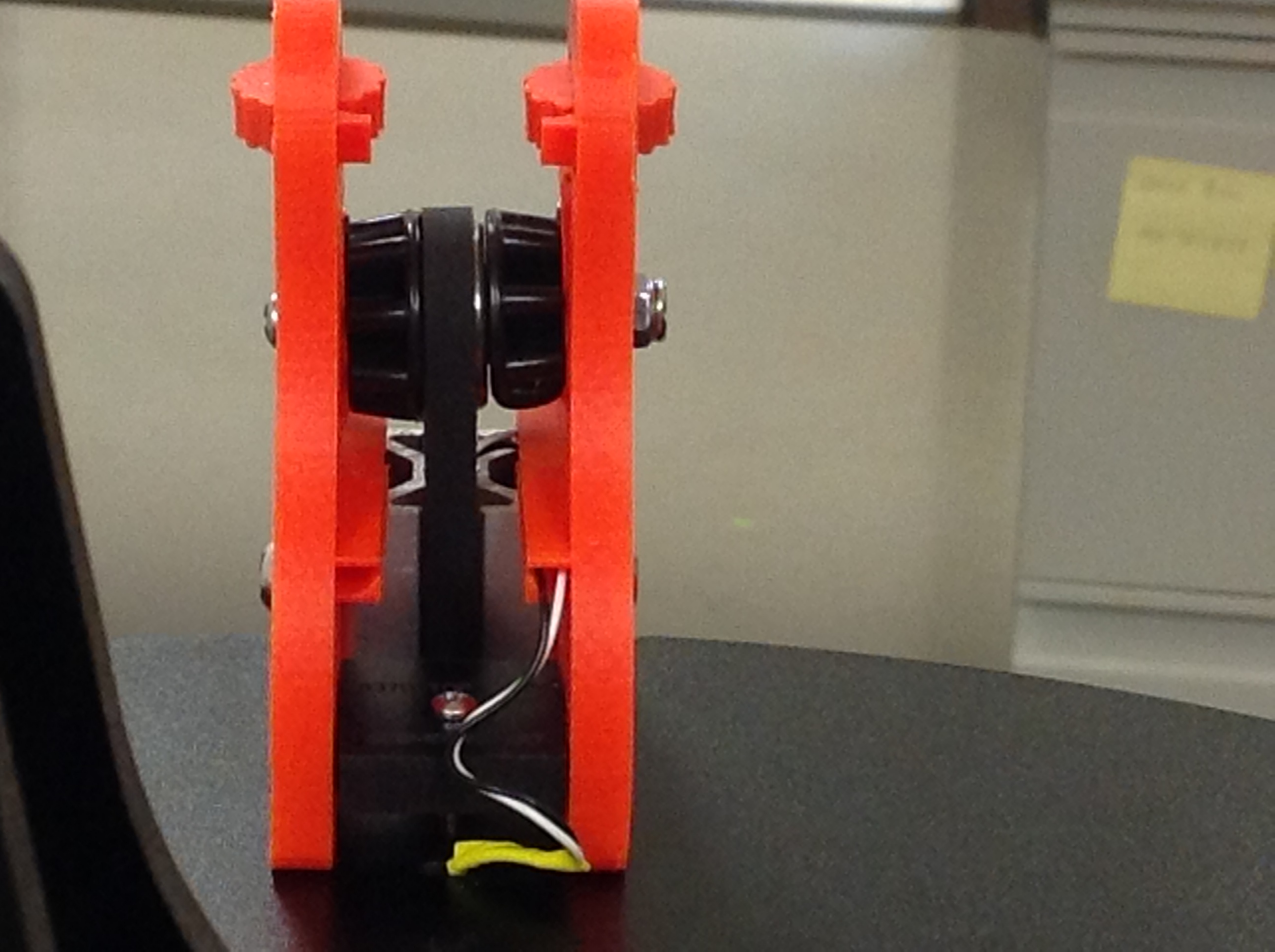
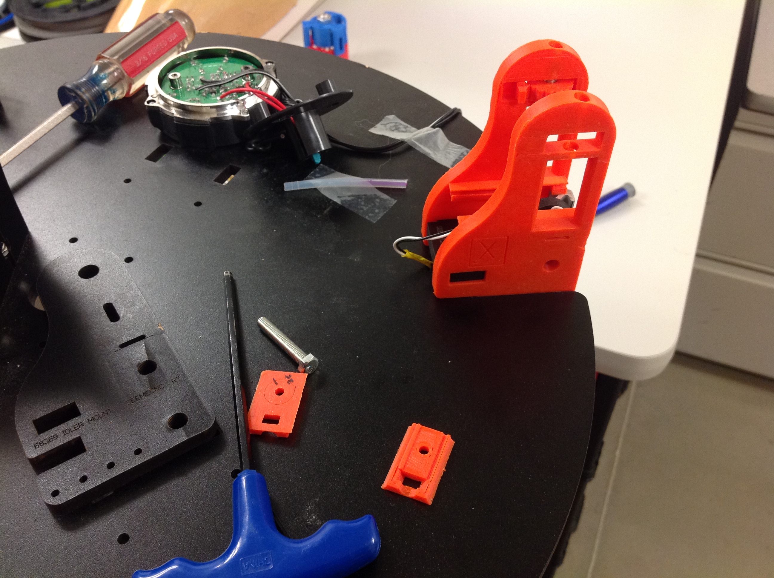
The Rostock MAX belt tensioners were OK but required tools and three hands to align the bearings, develop the tension and tighten in place. At TPM Technologies we developed a system for evenly tightening the belt from both sides and best of all, no tools required. A screw was used as a micro-adjuster. The screw head is trapped by two symmetric plates that ride up and down the plate where the nut is captured. The four traveling plates are held together with the screw that traps the bearing and spacers from the original design. The nut is encased in a knob with ridges. The ridges are locked with a spring printed into the plate. Now the belt can be tightened and equalized on both sides without tools. The design was done in SolidWorks and the parts printed in ABS on the Makerbot Replicator. The axis designation was also engrave printed into the side of the plate and each axis was color coded.IMG_3748IMG_3769IMG_3757 IMG_3767

3D Printing Projects 201402 – On the road to OrthoBot, Packt to the Rescue

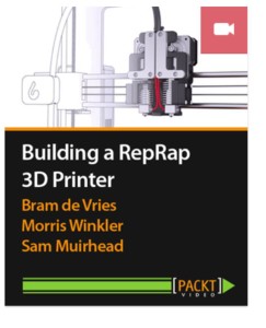
PacktVideoAt TPM Technologies we currently have a Makerbot Replicator and a Rostock Max. The build envelops are sufficient for most projects so far. Occasionally we have to get creative about placement or how to split a large assembly. It dawned on me that many part needs are long and slender but there isn’t a need to support an equilateral cube. Hence, we dubbed our large area printer “OrthoBot” as a way to describe this phenomenon. Think of a machine envelope required to print a femur, the largest bone in the body. That’s our quest. Or another way to think of it is the build envelope required to print a baseball bat. As we were kicking around approaches to this build envelope we happened across a new video on the Packt Publishing website, “Building a RepRap 3D Printer.”

I have to say I was totally impressed for several reasons. First, the quality of the video is inspiring. Having done many video projects over at StudioYouTube, I know how hard it is to make a good video. I was impressed by the videography and the ease of watching and how Sam Muirhead effectively used the video medium to pass along the content the rest of the team wanted to portray.

My next great surprise was that the Packt site would play the video just fine on my iPad so I could conveniently view it many places in my workshop, multi-tasking as I absorbed the sequence of the RepRap build.

Lastly, the content that the team put together is what every 3D printer builder can gain from. Even though they are using the i3 Berlin RepRap printer as the backdrop they have done a nice job of describing build elements and techniques that apply to many 3D printer build projects. Not only is the video full of nice technique but it is equally inspiring as you develop or build your own system. I found that once I started watching it was hard to stop. I kept sneaking away to finish watching to the end. My hat’s off to this team and their advancement of the open source 3D printing industry and RepRap. I’m sure many new applications will spawn from their efforts. You can check out the video here. More on OrthBot later.
3D Printing Projects 201401 – Printing Machine Part

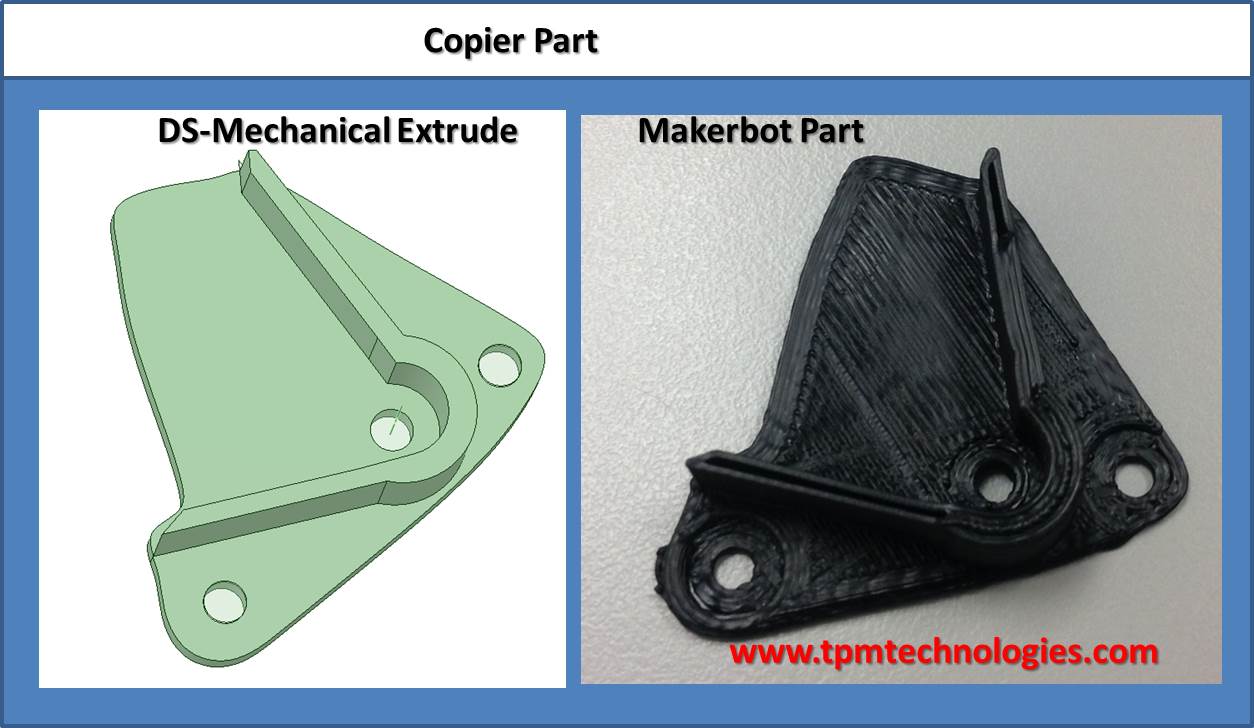
cpptA business acquaintance had a used but significant piece of equipment in their printing business and needed a replacement part. Using a picture with the part next to a scale the picture was imported into Design Spark Mechanical and the 2D profile was traced and then extruded to the correct depths. DS-Mechanical worked quite well for scaling, tracing, extruding, and exporting the stl file.

The part was designed in metric and printed in ABS on a Makerbot Replicator.

3D Printing Projects 201334 – Door Knob Keys reminder

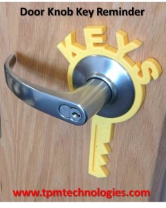
3dkeysSomeone was using a post-it note to remind themselves not to lock the keys in their office. We came up with a catchy solution. The round ring provides just enough friction that an adhesive was not needed. No sanding either!

The part was designed in SolidWorks and printed in ABS.

3D Printing Projects 201333 – UNEF Threaded extension

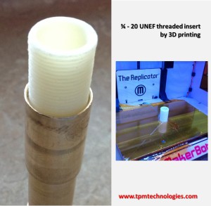
MB_3420A friend of min was having trouble sourcing quickly a fitting for a faucet project. The unit had a 3/4 – 20 UNEF (extra fine) thread. We looked up the threads specs and printed a couple of trials. The threads engage nice in general. There is a little swelling at the base where the part sits on the heated bed.

The pipe was designed in SolidWorks and printed in ABS.

3D Printing Projects 201332 – Rostock MAX upgrades – fan plugin

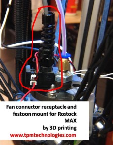
MB_RMfanThe fans for the Rostock come with tiny micro Molex connectors. The spacing is smaller than standard 0.1 inch header spacing. Wanting a sturdy end to the power festoon to the hot end a block was developed that engaged into the top mounting ring. Besides dowels that plug into the existing top plate a round cavity allows for a commercial strain relief to bring the power wire from the stationary part. A couple of square holes allow for plugging in of the micro Molex connectors. Wire was used to make pins guided by holds printed in the block. A groove to interlock the connector orientation was printed as well.

The block was designed in SolidWorks and printed in ABS.  Now the fans can be plugged in and the connection of the power wire to the hot end securely fastened.

3D Printing Projects 201331 – Rostock MAX updgrades – cooling

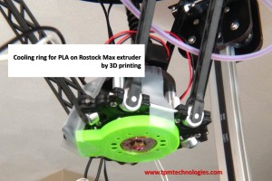
MB_RMcoolingIn getting the parameters dialed in for printing PLA a cooling ring is envisaged to cool the extruded material as it leaves the hot end. This mounts to the bottom of the Rostock Max extrusion platform. Internal baffles and differing size exit holes work to equalize the pressure to make a 360 degree cooling zone. A 25mm fan blows air from the side and gets directed to the printing interface. Eventually a set of clips will be integrated to clip on the axles of the delta unit.

The shroud was designed in SolidWorks and printed in ABS.  Once the shroud was in place a connection had to be developed for powering the fan. See later post.